ASRock 775V88 Quick Installation Guide - Page 16
ASRock, 775V88/775V88, Motherboard - + support cd
 |
View all ASRock 775V88 manuals
Add to My Manuals
Save this manual to your list of manuals |
Page 16 highlights
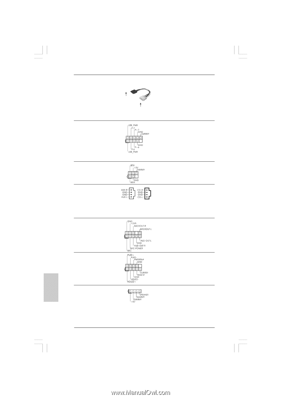
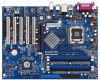
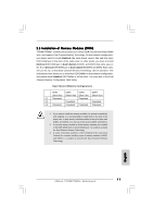
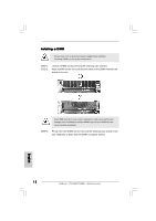
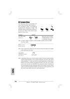
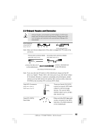
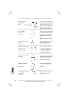
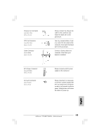
Serial ATA (SATA) Power Cable (Optional) connect to the SATA HDD power connector connect to the power supply Please connect the black end of SATA power cable to the power connector on the drive. Then connect the white end of SATA power cable to the power connector of the power supply. USB 2.0 Header (9-pin USB67) (see p.2, No. 18) ASRock I/O PlusTM provides you 6 ready-to-use USB 2.0 ports on the rear panel. If the rear USB ports are not sufficient, this USB 2.0 header is available to support 2 extra USB 2.0 ports. Infrared Module Header (5-pin IR1) (see p.2, No. 26) This header supports an optional wireless transmitting and receiving infrared module. Internal Audio Connectors (4-pin CD1, 4-pin AUX1) (CD1: see p.2, No. 20) (AUX1: see p.2, No. 23) AUX1 CD1 These connectors allow you to receive stereo audio input from sound sources such as a CD-ROM, DVD-ROM, TV tuner card, or MPEG card. Front Panel Audio Header (9-pin AUDIO1) (see p.2, No. 22) This is an interface for the front panel audio cable that allows convenient connection and control of audio devices. System Panel Header (9-pin PANEL1) (see p.2, No. 15) This header accommodates several system front panel functions. Chassis Speaker Header (4-pin SPEAKER 1) (see p.2, No. 16) Please connect the chassis speaker to this header. English 16 ASRock 775V88/775V88+ Motherboard
-
 1
1 -
2
-
3
-
4
-
5
-
6
-
7
-
8
-
9
-
10
-
 11
11 -
 12
12 -
 13
13 -
 14
14 -
 15
15 -
 16
16 -
 17
17 -
 18
18 -
 19
19 -
 20
20 -
 21
21 -
22
-
23
-
24
-
25
-
26
-
27
-
28
-
29
-
30
-
31
-
32
-
33
-
34
-
35
-
36
-
37
-
38
-
39
-
40
-
41
-
42
-
43
-
44
-
45
-
46
-
47
-
48
-
49
-
50
-
51
-
52
-
53
-
54
-
55
-
56
-
57
-
58
-
59
-
60
-
61
-
62
-
63
-
64
-
65
-
66
-
67
-
68
-
69
-
70
-
71
-
72
-
73
-
74
-
75
-
76
-
77
-
78
-
79
-
80
-
81
-
82
-
83
-
84
-
85
-
86
-
87
-
88
-
89
-
90
-
91
-
92
-
93
-
94
-
95
-
96
-
97
-
98
-
99
-
100
-
101
-
102
-
103
-
104
-
105
-
106
-
107
-
108
-
109
-
110
-
111
-
112
-
113
-
114
 |
 |