ASRock 775i65G Quick Installation Guide - Page 17
English, Serial A, Serial ATA SA, A SATA Hard Disks Installation, A Hard Disks Installation, Driver - support list
 |
View all ASRock 775i65G manuals
Add to My Manuals
Save this manual to your list of manuals |
Page 17 highlights
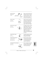
Serial port connector (9-pin COM1) (see p.2 No. 20) This COM1 connector supports a serial port module. 2.7 Serial ATA (SATA) Hard Disks Installation This motherboard adopts Intel® ICH5 south bridge chipset that supports Serial ATA (SATA) hard disks. You may install SATA hard disks on this motherboard for internal storage devices. This section will guide you to install the SATA hard disks. STEP 1: Install the SATA hard disks into the drive bays of your chassis. STEP 2: Connect the SATA power cable to the SATA hard disk. STEP 3: Connect one end of the SATA data cable to the motherboard's primary SATA connector (SATA1). STEP 4: Connect the other end of the SATA data cable to the primary SATA hard disk. If you just want to install only one SATA HDD, the installation process is complete at this step. If you want to install two SATA HDDs, please continue to do the following steps. STEP 5: Connect the SATA power cable to the SATA hard disk. STEP 6: Connect one end of the second SATA data cable to the motherboard's secondary SATA connector (SATA2). STEP 7: Connect the other end of the SATA data cable to the secondary SATA hard disk. Before you install OS into the SATA hard disk, you need to check and ensure the configuration of the OnBoard IDE Operate Mode option in BIOS setup is correct according to the condition of your system. For the configuration details, please refer to the instruction on page 29 of "User Manual" in the support CD. 2.8 Driver Installation Guide To install the drivers to your system, please insert the support CD to your optical drive first. Then, the drivers compatible to your system can be auto-detected and listed on the support CD driver page. Please follow the order from up to bottom side to install those required drivers. Therefore, the drivers you install can work properly. 17 ASRock 775i65G Motherboard English
-
 1
1 -
2
-
3
-
4
-
5
-
6
-
7
-
8
-
9
-
10
-
11
-
 12
12 -
 13
13 -
 14
14 -
 15
15 -
 16
16 -
 17
17 -
 18
18 -
 19
19 -
 20
20 -
 21
21 -
 22
22 -
23
-
24
-
25
-
26
-
27
-
28
-
29
-
30
-
31
-
32
-
33
-
34
-
35
-
36
-
37
-
38
-
39
-
40
-
41
-
42
-
43
-
44
-
45
-
46
-
47
-
48
-
49
-
50
-
51
-
52
-
53
-
54
-
55
-
56
-
57
-
58
-
59
-
60
-
61
-
62
-
63
-
64
-
65
-
66
-
67
-
68
-
69
-
70
-
71
-
72
-
73
-
74
-
75
-
76
-
77
-
78
-
79
-
80
-
81
-
82
-
83
-
84
-
85
 |
 |
