ASRock 775i915P-SATA2 User Manual - Page 24
Please connect an ATX 12V
 |
View all ASRock 775i915P-SATA2 manuals
Add to My Manuals
Save this manual to your list of manuals |
Page 24 highlights
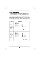
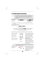
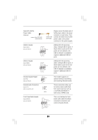
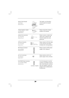
System Panel Header (9-pin PANEL1) (see p.10 No. 19) Chassis Speaker Header (4-pin SPEAKER 1) (see p.10 No. 21) Chassis Fan Connector (3-pin CHA_FAN1) (see p.10 No. 20) CPU Fan Connector (4-pin CPU_FAN1) (see p.10 No. 5) ATX Power Connector (20-pin ATXPWR1) (see p.10 No. 38) PLED+ PLEDPWRBTN# GND 1 DUMMY RESET# GND HDLEDHDLED+ 1 SPEAKER DUMMY DUMMY +5V This header accommodates several system front panel functions. Please connect the chassis speaker to this header. GND +12V CHA_FAN_SPEED Please connect a chassis fan cable to this connector and match the black wire to the ground pin. GND +12V CPU_FAN_SPEED FAN_SPEED_CONTROL Please connect a CPU fan cable to this connector and match the black wire to the ground pin. Please connect an ATX power supply to this connector. ATX 12V Connector (4-pin ATX12V1) (see p.10 No. 2) Please connect an ATX 12V power supply to this connector. SLI/XFIRE Power Connector (4-pin SLI/XFIRE_POWER1) (see p.10 No. 36) SLI/XFIRE_POWER1 It is not necessary to use this connector, but please connect it with a hard disk power connecor when two graphics cards are plugged to this motherboard at the same time. 24
-
 1
1 -
2
-
3
-
4
-
5
-
6
-
7
-
8
-
9
-
10
-
11
-
12
-
13
-
14
-
15
-
16
-
17
-
18
-
 19
19 -
 20
20 -
 21
21 -
 22
22 -
 23
23 -
 24
24 -
 25
25 -
 26
26 -
 27
27 -
 28
28 -
 29
29 -
30
-
31
-
32
-
33
-
34
-
35
-
36
-
37
-
38
-
39
-
40
-
41
-
42
 |
 |
