ASRock 775i915PL-M User Manual
ASRock 775i915PL-M Manual
 |
View all ASRock 775i915PL-M manuals
Add to My Manuals
Save this manual to your list of manuals |
ASRock 775i915PL-M manual content summary:
- ASRock 775i915PL-M | User Manual - Page 1
775i915PL-M User Manual Version 1.0 Published May 2005 Copyright©2005 ASRock INC. All rights reserved. 1 - ASRock 775i915PL-M | User Manual - Page 2
any form or by any means, except duplication of documentation by the purchaser for backup purpose, without written consent of ASRock Inc. Products and corporate names appearing in this manual may or may not be registered trademarks or copyrights of their respective companies, and are used only for - ASRock 775i915PL-M | User Manual - Page 3
Introduction 5 1.1 Package Contents 5 1.2 Specifications 6 1.3 Motherboard Layout 8 1.4 ASRock 8CH I/O 9 2 Installation 10 2.1 Screw Holes Connectors 17 2.10 Serial ATA (SATA) Hard Disks Installation 20 3 BIOS SETUP UTILITY 21 3.1 Introduction 23 3.1.1 BIOS Menu Bar 23 3.1.2 Navigation - ASRock 775i915PL-M | User Manual - Page 4
4 Software Support 36 4.1 Install Operating System 36 4.2 Support CD Information 36 4.2.1 Running Support CD 36 4.2.2 Drivers Menu 36 4.2.3 Utilities Menu 36 4.2.4 "LGA 775 CPU Installation Live Demo" Program .. 36 4.2.5 Contact Information 36 4 - ASRock 775i915PL-M | User Manual - Page 5
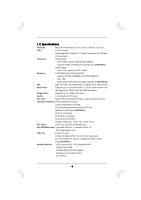
and CPU support lists on ASRock website as well. ASRock website http://www.asrock.com 1.1 Package Contents ASRock 775i915PL-M Motherboard (Micro ATX Form Factor: 9.6-in x 8.6-in, 24.4 cm x 21.8 cm) ASRock 775i915PL-M Quick Installation Guide ASRock 775i915PL-M Support CD (including LGA 775 CPU - ASRock 775i915PL-M | User Manual - Page 6
x 21.8 cm CPU: 775-Pin Socket supporting Intel® Pentium® 4 / Celeron® processor (in 775-land LGA package) Chipsets: North Bridge: Intel® 915PL chipset, FSB @ 800 / 533MHz, supports Hyper-Threading Technology (see CAUTION 1) South Bridge: Intel® ICH6, supports SATA 1.5Gb/s Memory: 2 DDR - ASRock 775i915PL-M | User Manual - Page 7
Although this motherboard offers stepless control, it is not recommended to perform over-clocking. Frequencies other than the recommended CPU bus frequencies may cause the instability of the system or damage the CPU. 7. Because of Intel 915PL chipset limitation, Windows 98 / ME does not support USB - ASRock 775i915PL-M | User Manual - Page 8
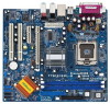
CLRCMOS1 1 USB45 PANEL1 PLED PWRBTN 1 HDLED RESET SATA1 SATA2 SATA3 SATA4 775i915PL-M PCI EXPRESS 24.4cm (9.6 in) 8 9 10 11 12 13 22 21 20 19 18 17 161514 1 PS2_USB_PWR1 Jumper 2 ATX 12V Connector (ATX12V1) 3 775-Pin CPU Socket 4 North Bridge Controller 5 CPU Fan Connector (CPU_FAN1) 6 184 - ASRock 775i915PL-M | User Manual - Page 9
1.4 ASRock 8CH I/O 1 13 12 11 2 3 6 4 7 5 8 10 9 1 Parallel Port 2 RJ-45 Port 3 Side Speaker (Gray) 4 Rear Speaker (Black) 5 Central / Bass (Orange) 6 Line In (Light Blue) * 7 Front Speaker ( - ASRock 775i915PL-M | User Manual - Page 10
Precautions Take note of the following precautions before you install motherboard components or change any motherboard settings. 1. Unplug the power cord from the wall socket before touching any component. 2. To avoid damaging the motherboard components due to static electricity, NEVER place your - ASRock 775i915PL-M | User Manual - Page 11
2.3 CPU Installation For the installation of Intel 775-LAND CPU, please follow the steps below. 775-Pin Socket Overview Before you insert the 775-LAND CPU into the socket, please check if the CPU surface is unclean or if there is any bent pin on the socket. Do not force to insert the CPU into the - ASRock 775i915PL-M | User Manual - Page 12
finger and thumb to support the load plate edge, engage PnP cap with right hand thumb and peel the cap from the socket while pressing on center cap. 2. This cap must be placed if returning the motherboard for after service. Step 4. Close the socket: Step 4-1. Rotate the load plate onto the IHS. - ASRock 775i915PL-M | User Manual - Page 13
2.4 Installation of CPU Fan and Heatsink This motherboard is equipped with 775-Pin socket that supports Intel 775-LAND CPU. Please adopt the type of heatsink and cooling fan compliant with Intel 775-LAND CPU to dissipate heat. Before you installed the heatsink, you need to spray thermal interface - ASRock 775i915PL-M | User Manual - Page 14
2.5 Installation of Memory Modules (DIMM) 775i915PL-M motherboard provides two 184-pin DDR (Double Data Rate) DIMM slots, and supports Dual Channel Memory Technology. For dual channel configuration, you always need to install two identical (the same brand, speed, size and chip-type) memory modules - ASRock 775i915PL-M | User Manual - Page 15
There are 2 PCI slots and 2 PCI Express slot on this motherboard. PCI slots: PCI slots are used to install expansion cards that (PCIE x4 slot) is used for PCI Express cards, such as GigaLAN card, SATA2 card, etc. Installing an expansion card Step 1. Before installing the expansion card, please - ASRock 775i915PL-M | User Manual - Page 16
Display Feature This motherboard supports Surround Display upgrade. With the external add-on PCI Express VGA card, you can easily enjoy the benefits of Surround Display feature. For the detailed instruction, please refer to the document at the following path in the Support CD: ..\ Surround Display - ASRock 775i915PL-M | User Manual - Page 17
damage of the motherboard! FDD connector ( instruction of your IDE device vendor for the details. Serial ATA Connectors (SATA1: see p.8 No. 17) (SATA2: see p.8 No. 16) (SATA3: see p.8 No. 15) (SATA4: see p.8 No. 14) SATA1 SATA2 SATA3 SATA4 These four Serial ATA (SATA) connectors support SATA - ASRock 775i915PL-M | User Manual - Page 18
connect the black end of SATA power cable to the power connector on each drive. Then connect the white end of SATA power cable to the USB_PWR ASRock 8CH I/O accommodates 4 default USB 2.0 ports. If those USB 2.0 ports on the I/O panel are not sufficient, this USB 2.0 header is available to support - ASRock 775i915PL-M | User Manual - Page 19
System Panel Header (9-pin PANEL1) (see p.8 No. 18) Chassis Speaker Header (4-pin SPEAKER 1) (see p.8 No. 13) Chassis Fan Connector (3-pin CHA_FAN1) (see p.8 No. 10) CPU Fan Connector (4-pin CPU_FAN1) (see p.8 No. 5) ATX Power Connector (20-pin ATXPWR1) (see p.8 No. 28) PLED+ PLEDPWRBTN# GND 1 - ASRock 775i915PL-M | User Manual - Page 20
adopts Intel ICH6 south bridge chipset that supports Serial ATA (SATA) hard disks. You may install SATA hard disks on this motherboard for internal storage devices. This section will guide you to install the SATA hard disks. STEP 1: Install the SATA hard disks into the drive bays of your chassis - ASRock 775i915PL-M | User Manual - Page 21
UTILITY 3.1 Introduction This section explains how to use the BIOS SETUP UTILITY to configure your system. The BIOS FWH chip on the motherboard stores the BIOS SETUP UTILITY. You may run the BIOS SETUP UTILITY when you start up the computer. Please press during the Power-On-Self-Test (POST - ASRock 775i915PL-M | User Manual - Page 22
SETUP UTILITY Main Advanced H/W Monitor Boot Security Exit System Overview System Time System Date [14:00:09] [Thu 05/05/2005] BIOS Version : 775i915PL-M BIOS P1.00 Processor Type : Intel (R) CPU 3.60 GHz Processor Speed : 3600 MHz Microcode Update : F43/04 Cache Size : 2048KB Total - ASRock 775i915PL-M | User Manual - Page 23
Save and Exit Exit v02.54 (C) Copyright 1985-2005, American Megatrends, Inc. CPU Host Frequency While entering setup, BIOS auto detects the present CPU host frequency of this motherboard. The actual CPU host frequency will show in the following item. Boot Failure Guard Enable or disable the feature - ASRock 775i915PL-M | User Manual - Page 24
allow you changing the ratio value of this motherboard. If it shows "Locked", then the support No-Excute Memory Protection. Enhance Halt State All processors support the Halt State (C1). The C1 state is supported through the native processor instructions HLT and MWAIT and requires no hardware support - ASRock 775i915PL-M | User Manual - Page 25
3.3.2 Chipset Configuration BIOS SETUP UTILITY Advanced Chipset Configuration DRAM Frequency [Auto] Flexibility 2005, American Megatrends, Inc. DRAM Frequency If [Auto] is selected, the motherboard will detect the memory module(s) inserted and assigns appropriate frequency automatically. You may - ASRock 775i915PL-M | User Manual - Page 26
is [Auto]. VDDQ Use this to select VDDQ. Configuration options: [High], and [Low]. The default value of this feature is [Low]. 3.3.3 ACPI Configuration BIOS SETUP UTILITY Advanced ACPI Configuration Suspend To RAM Restore on AC/Power Loss Ring-In Power On PCI Devices Power On PS / 2 Keyboard - ASRock 775i915PL-M | User Manual - Page 27
only supports four IDE devices under legacy OS (Windows ME / 98SE / NT), you have to choose [SATA 1, SATA 2, SATA 3, SATA 4], or [IDE 1, SATA 2, SATA 4] when the installed device is used with legacy OS. [SATA 1, SATA 2, SATA 3, SATA 4] [IDE 1, SATA 2, SATA 4] Master SATA1, SATA2 SATA2 Slave - ASRock 775i915PL-M | User Manual - Page 28
Master" as the example in the following instruction. BIOS SETUP UTILITY Advanced Primary IDE Master Device Vendor Disk :ST340014A :40.0 GB :Supported :16Sectors :4 :MultiWord DMA-2 :Ultra DMA-5 :Supported [Auto] [Auto] [Auto] MB under DOS and Windows; for Netware and UNIX user, select [Disabled] to - ASRock 775i915PL-M | User Manual - Page 29
32-Bit Data Transfer Use this item to enable 32-bit access to maximize the IDE hard disk data transfer rate. 3.3.5 PCIPnP Configuration BIOS SETUP UTILITY Advanced PCI / PnP Configuration WARNING: Setting wrong values in below actions may cause system to malfunction. PCI Latency Timer PCI IDE - ASRock 775i915PL-M | User Manual - Page 30
3.3.6 Floppy Configuration In this section, you may configure the type of your floppy drive. BIOS SETUP UTILITY Advanced Floppy Configuration Floppy A [1.44 MB 312"] Select the type of floppy drive connected to the system. +F1 F9 F10 ESC Select Screen Select Item Change Option General Help - ASRock 775i915PL-M | User Manual - Page 31
Parallel Port Address Use this item to set the address for the onboard parallel port or disable it. Configuration options: [Disabled], [378], and [278]. Parallel Port Mode Use this item to set the operation mode of the parallel port. The default value is [ECP+EPP]. If this option is set to [ECP+EPP - ASRock 775i915PL-M | User Manual - Page 32
there is no USB device connected, "Auto" option will disable the legacy USB support. 3.4 Hardware Health Event Monitoring Screen In this section, it allows you to monitor CPU temperature, motherboard temperature, CPU fan speed, chassis fan speed, and the critical voltage. BIOS SETUP UTILITY Main - ASRock 775i915PL-M | User Manual - Page 33
it will display the available devices on your system for you to configure the boot settings and the boot priority. Main Advanced BIOS SETUP UTILITY H/W Monitor Boot Security Exit Boot Settings Boot Settings Configuration Configure Settings during System Boot. 1st Boot Device 2nd Boot Device - ASRock 775i915PL-M | User Manual - Page 34
you may set or change the supervisor/user password for the system. For the user password, you may also clear it. BIOS SETUP UTILITY Main Advanced H/W Monitor Boot Security Exit Security Settings Supervisor Password : Not Installed User Password : Not Installed Change Supervisor Password - ASRock 775i915PL-M | User Manual - Page 35
and exit setup?" Select [OK] to save the changes and exit the BIOS SETUP UTILITY. Discard Changes and Exit When you select this option, it message, "Discard changes and exit setup?" Select [OK] to exit the BIOS SETUP UTILITY without saving any changes. Discard Changes When you select this option - ASRock 775i915PL-M | User Manual - Page 36
Live Demo" Program This motherboard is equipped with Intel LGA 775 socket, which is a new CPU socket interface that Intel has released. Since it has several tiny pins, whcih are easily to be damaged by improper handling, ASRock sincerely presents you a clear installation guide through this "LGA
-
 1
1 -
 2
2 -
 3
3 -
 4
4 -
 5
5 -
 6
6 -
 7
7 -
8
-
9
-
10
-
11
-
12
-
13
-
14
-
15
-
16
-
17
-
18
-
19
-
20
-
21
-
22
-
23
-
24
-
25
-
26
-
27
-
28
-
29
-
30
-
31
-
32
-
33
-
34
-
35
-
36
 |
 |

1
775i915PL-M
User Manual
Version 1.0
Published May 2005
Copyright©2005 ASRock INC. All rights reserved.