ASRock 870 Extreme3 User Manual
ASRock 870 Extreme3 Manual
 |
View all ASRock 870 Extreme3 manuals
Add to My Manuals
Save this manual to your list of manuals |
ASRock 870 Extreme3 manual content summary:
- ASRock 870 Extreme3 | User Manual - Page 1
870 Extreme3 User Manual Version 1.0 Published April 2010 Copyright©2010 ASRock INC. All rights reserved. 1 - ASRock 870 Extreme3 | User Manual - Page 2
commitment by ASRock. ASRock assumes no responsibility for any errors or omissions that may appear in this manual. With respect to the contents of this manual, ASRock does not , USA ONLY The Lithium battery adopted on this motherboard contains Perchlorate, a toxic substance controlled in Perchlorate - ASRock 870 Extreme3 | User Manual - Page 3
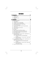
2.2 Installation of CPU Fan and Heatsink 14 2.3 Installation of Memory Modules (DIMM 15 2.4 Expansion Slots (PCI and PCI Express Slots 17 2.5 Surround Display Feature 18 2.6 CrossFireXTM and Quad CrossFireXTM Operation Guide .......... 22 2.7 Jumpers Setup 23 2.8 Onboard Headers and Connectors - ASRock 870 Extreme3 | User Manual - Page 4
Screen 58 3.6 Boot Screen 59 3.6.1 Boot Settings Configuration 59 3.7 Security Screen 60 3.8 Exit Screen 61 4 . Software Support 62 4.1 Install Operating System 62 4.2 Support CD Information 62 4.2.1 Running Support CD 62 4.2.2 Drivers Menu 62 4.2.3 Utilities Menu 62 4.2.4 Contact - ASRock 870 Extreme3 | User Manual - Page 5
guide to BIOS setup and information of the Support CD. Because the motherboard specifications and the BIOS software might be updated, the content of this manual will be subject to change without notice. In case any modifications of this manual occur, the updated version will be available on ASRock - ASRock 870 Extreme3 | User Manual - Page 6
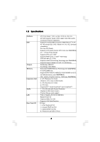
1.2 Specifications Platform CPU Chipset Memory Expansion Slot Audio LAN Rear Panel I/O - ATX Form Factor: 12.0-in x 9.6-in, 30.5 cm x 24.4 cm - All Solid Capacitor design (100% Japan-made high-quality Conductive Polymer Capacitors) - Support for Socket AM3 processors: AMD PhenomTM II X4 / X3 / X2 - ASRock 870 Extreme3 | User Manual - Page 7
/s connectors - 1 x IR header - 1 x COM port header - 1 x IEEE 1394 header - 1 x HDMI_SPDIF header - 1 x Power LED header - CPU/Chassis/Power FAN connector - 24 pin ATX power connector - 8 pin 12V power connector - Front panel audio connector - 3 x USB 2.0 headers (support 6 USB 2.0 ports) - 1 x Dr - ASRock 870 Extreme3 | User Manual - Page 8
ready power supply is required) (see CAUTION 13) * For detailed product information, please visit our website: http://www.asrock.com WARNING Please realize that there is a certain risk involved with overclocking, including adjusting the setting in the BIOS, applying Untied Overclocking Technology - ASRock 870 Extreme3 | User Manual - Page 9
. 4. Whether 1800/1600MHz memory speed is supported depends on the AM3 CPU you adopt. If you want to adopt DDR3 1800/1600 memory module on this motherboard, please refer to the memory support list on our website for the compatible memory modules. ASRock website http://www.asrock.com 5. Due to the - ASRock 870 Extreme3 | User Manual - Page 10
like MS-DOS or Windows®. With this utility, you can press key during the POST or press key to BIOS setup menu to access ASRock Instant Flash. Just launch this tool and save the new BIOS file to your USB flash drive, floppy disk or hard drive, then you can update your BIOS only in a few - ASRock 870 Extreme3 | User Manual - Page 11
1800 RJ-45 LAN USB 3.0 T: USB0 B: USB1 NEC MPD720200 LAN PHY AUDIO CODEC HD_AUDIO1 1 Super I/O HDMI_SPDIF1 1 IR1 1 CHA_FAN3 CHA_FAN2 AMD 870 Chipset PCIE1 Six-Core CPU Ready PCIE2 PCI Express 2.0 870 Extreme3 NEC USB 3.0 SATA3_4_5 PCIE3 CMOS BATTERY 8Mb BIOS PCIE4 AMD SB850 Chipset - ASRock 870 Extreme3 | User Manual - Page 12
USB 2.0 Ports (USB01) 2 USB 2.0 Ports (USB45) * 3 LAN RJ-45 Port 4 Side Speaker (Gray) 5 Rear Speaker (Black) 6 Central / Bass (Orange) 7 Line In (Light Blue) ** 8 Front Speaker (Lime) 9 Microphone (Pink) 13 12 11 10 10 USB front panel audio cable to the front panel audio header. After restarting - ASRock 870 Extreme3 | User Manual - Page 13
any motherboard settings. Before you install or remove any component, ensure that the power is switched off or the power cord is detached from the power supply. Failure to do so may cause severe damage to the motherboard, peripherals, and/or components. 1. Unplug the power cord from the wall socket - ASRock 870 Extreme3 | User Manual - Page 14
. Make sure that the CPU and the heatsink are securely fastened and in good contact with each other. Then connect the CPU fan to the CPU FAN connector (CPU_FAN1, see Page 11, No. 7). For proper installation, please kindly refer to the instruction manuals of the CPU fan and the heatsink. 14 - ASRock 870 Extreme3 | User Manual - Page 15
same color. In other words, install them either in the set of blue slots (DDR3_A1 and DDR3_B1), or in the set of white slots (DDR3_A2 and DDR3_B2). 2. If only one memory module or three memory modules are installed in the DDR3 DIMM slots on this motherboard, it is unable to activate the Dual Channel - ASRock 870 Extreme3 | User Manual - Page 16
Please make sure to disconnect power supply before adding or removing DIMMs or the system components. Step 1. Step 2. Unlock a DIMM slot by pressing the retaining clips outward. Align a DIMM on the slot such that the notch on the DIMM matches the break on the slot. notch break notch break The - ASRock 870 Extreme3 | User Manual - Page 17
make sure that the power supply is switched off or the power cord is unplugged. Please read the documentation of the expansion card and make necessary hardware settings for the card before you start the installation. Step 2. Remove the system unit cover (if your motherboard is already installed in - ASRock 870 Extreme3 | User Manual - Page 18
3D application. Currently CrossFireXTM feature is supported with Windows® XP with Service Pack 2 / VistaTM / 7 OS. Quad CrossFireXTM feature are supported with Windows® VistaTM / 7 OS only. Please check AMD website for ATITM CrossFireXTM driver updates. 1. If a customer incorrectly configures their - ASRock 870 Extreme3 | User Manual - Page 19
Bridge is provided with the graphics card you purchase, not bundled with this motherboard. Please refer to your graphics card vendor for details.) CrossFire Bridge or Step 3. Connect the DVI monitor cable to the DVI connector on the Radeon graphics card on PCIE2 slot. (You may use the DVI to - ASRock 870 Extreme3 | User Manual - Page 20
prior to installation. Please check AMD website for ATITM driver updates. Step 3. Step 4. Step 5. Install the required drivers to your system. For Windows® XP OS: A. ATITM recommends Windows® XP Service Pack 2 or higher to be installed (If you have Windows® XP Service Pack 2 or higher installed in - ASRock 870 Extreme3 | User Manual - Page 21
is used only for identification or explanation and to the owners' benefit, without intent to infringe. * For further information of ATITM CrossFireXTM technology, please check AMD website for updates and details. 21 - ASRock 870 Extreme3 | User Manual - Page 22
Display Feature This motherboard supports Surround Display upgrade. With the external add-on PCI Express VGA cards, you can easily enjoy the benefits of Surround Display feature. For the detailed instruction, please refer to the document at the following path in the Support CD: ..\ Surround Display - ASRock 870 Extreme3 | User Manual - Page 23
Note: To select +5V_DUAL, it requires 2 Amp and higher standby current provided by power supply. When you select +5V_DUAL, USB devices can wake up the system under S3 (Suspend to RAM) state. To support ErP/EuP requirement, please set this jumper to +5V. USB_PW3 (see p.11, No. 27) 1_2 +5V 2_3 - ASRock 870 Extreme3 | User Manual - Page 24
1 GND P+10 P-10 USB_PWR Either end of the SATA data cable can be connected to the SATA3 hard disk or the SATA3 connector on this motherboard. Besides six default USB 2.0 ports on the I/O panel, there are three USB 2.0 headers on this motherboard. Each USB 2.0 header can support two USB 2.0 ports - ASRock 870 Extreme3 | User Manual - Page 25
but the panel wire on the chassis must support HDA to function correctly. Please follow the instruction in our manual and chassis manual to install your system. 2. If you use AC'97 audio panel, please install it to the front panel audio header as below: A. Connect Mic_IN (MIC) to MIC2_L. B. Connect - ASRock 870 Extreme3 | User Manual - Page 26
CPU fan (Quiet Fan) support, the 3-Pin CPU fan still can work successfully even without the fan speed control function. If you plan to connect the 3-Pin CPU fan to the CPU fan connector on this motherboard, please connect it to Pin 1-3. Pin 1-3 Connected 3-Pin Fan Installation ATX Power Connector - ASRock 870 Extreme3 | User Manual - Page 27
an ATX 12V power supply to this connector. Though this motherboard provides 8-pin ATX 12V power connector, it can still work if you adopt a traditional 4-pin ATX 12V power supply. To use the 4-pin ATX power supply, please plug your power supply along with Pin 1 and Pin 5. 8 5 IEEE 1394 Header - ASRock 870 Extreme3 | User Manual - Page 28
motherboard has three smart switches: power switch, reset switch and clear CMOS switch, allowing users to quickly turn on/off or reset the system or clear the CMOS values. Power Switch (PWRBTN) (see p.11 No. 24) Power to use Clear CMOS switch function if you set up the system password. If you want - ASRock 870 Extreme3 | User Manual - Page 29
Debug codes. The Bootblock initialization code sets up the chipset, memory and other components before system memory is available. The following table describes the type of checkpoints that may occur during the bootblock initialization portion of the BIOS: Checkpoint Before D1 D1 D0 D2 D3 D4 D5 D6 - ASRock 870 Extreme3 | User Manual - Page 30
. Verify CMOS checksum manually by reading storage area. If the CMOS checksum is bad, update CMOS with power-on default values and clear passwords. Initialize status register A. Initializes data variables that are based on CMOS setup questions. Initializes both the 8259 compatible PICs in the system - ASRock 870 Extreme3 | User Manual - Page 31
to the user and gets the user response for error. 87 Execute BIOS setup if needed / requested. 8C Late POST initialization of chipset registers. 8D Build ACPI tables (if ACPI is supported) 8E Program the peripheral parameters. Enable/Disable NMI as selected 90 Late POST initialization - ASRock 870 Extreme3 | User Manual - Page 32
Serial ATA3 (SATA3) Hard Disks Installation This motherboard adopts AMD SB850 chipset that supports Serial ATA3 (SATA3) hard disks and RAID functions. You may install SATA3 hard disks on this motherboard for internal storage devices. This section will guide you to install the SATA3 hard disks. STEP - ASRock 870 Extreme3 | User Manual - Page 33
is installed into system properly. The latest SATA3 driver is available on our support website: www.asrock.com 4. Make sure to use the SATA power cable & data cable, which are from our motherboard package. 5. Please follow below instructions step by step to reduce the risk of HDD crash or data - ASRock 870 Extreme3 | User Manual - Page 34
do follow below instruction sequence to process the Hot Plug, improper procedure will cause the SATA3 HDD damage and data loss. Step 1 Please connect SATA power cable 1x4-pin end Step 2 Connect SATA data cable to (White) to the power supply 1x4-pin cable. the motherboard's SATA3 connector. SATA - ASRock 870 Extreme3 | User Manual - Page 35
follow below steps. STEP 1: Set up BIOS. A. Enter BIOS SETUP UTILITY Advanced screen Storage Configuration. B. Set the "SATA Operation Mode" option to [RAID]. STEP 2: Make a SATA3 Driver Diskette. (Please use USB floppy or floppy disk.) A. Insert the ASRock Support CD into your optical - ASRock 870 Extreme3 | User Manual - Page 36
A. Enter BIOS SETUP UTILITY Advanced screen Storage Configuration. B. Set the "SATA Operation Mode" option to [RAID]. STEP 2: Use "RAID Installation Guide" to set RAID configuration. Before you start to configure RAID function, you need to check the RAID installation guide in the Support CD - ASRock 870 Extreme3 | User Manual - Page 37
mode) STEP 1: Set Up BIOS. A. Enter BIOS SETUP UTILITY Advanced screen Storage Configuration. B. Set the "SATA Operation Mode" option to [AHCI]. STEP 2: Make a SATA3 Driver Diskette. Make a SATA3 driver diskette by following section 2.15.1 step 2 on page 35. STEP 3: Install Windows® XP / XP - ASRock 870 Extreme3 | User Manual - Page 38
STEP 1: Set up BIOS. A. Enter BIOS SETUP UTILITY Advanced screen Storage Configuration. B. Set the "SATA Operation Mode" option to [IDE]. STEP 2: Install Windows® 7 / 7 64-bit / VistaTM / VistaTM 64-bit OS on your system. 2.17 Untied Overclocking Technology This motherboard supports Untied - ASRock 870 Extreme3 | User Manual - Page 39
This section explains how to use the BIOS SETUP UTILITY to configure your system. The SPI Memory on the motherboard stores the BIOS SETUP UTILITY. You may run the BIOS SETUP UTILITY when you start up the computer. Please press or during the Power-On-Self-Test (POST) to enter the - ASRock 870 Extreme3 | User Manual - Page 40
values for all the settings To save changes and exit the BIOS SETUP UTILITY To jump to BIOS Version : 870 Extreme3 P1.00 Processor Type : AMD Phenom(tm) II X2 555 Processor (64bit) Processor Speed : 3200MHz Microcode Update : 100F43/10000B6 L1 Cache Size : 256KB L2 Cache Size : 2048KB Total Memory - ASRock 870 Extreme3 | User Manual - Page 41
BIOS SETUP UTILITY Main OC Tweaker Advanced H/W Monitor Boot Security Exit EZ Overclocking Load Optimized CPU OC Setting [Press Enter] CPU Configuration Overclock Mode CPU Frequency (MHZ) PCIE Frequency (MHz) Spread Spectrum Boot Failure Guard Boot Failure Guard Count ASRock UCC CPU Active Core - ASRock 870 Extreme3 | User Manual - Page 42
BIOS SETUP UTILITY Main OC Tweaker Advanced H/W Monitor Boot Security Exit EZ Overclocking Load Optimized CPU OC Setting [Press Enter] CPU Configuration Overclock Mode CPU Frequency (MHZ) PCIE Frequency (MHz) Spread Spectrum Boot Failure Guard Boot Failure Guard Count ASRock UCC CPU Active Core - ASRock 870 Extreme3 | User Manual - Page 43
Hyper-Transport bus width. Configuration options: [Auto], [8 Bit] and [16 Bit]. Memory Configuration Memory Clock This item can be set by the code using [Auto]. You can set one of the standard values as listed: [400MHz DDR3_800], [533MHz DDR3_1066], [667MHz DDR3_1333] and [800MHz DDR3_1600]. DRAM - ASRock 870 Extreme3 | User Manual - Page 44
Memory Timing BIOS SETUP UTILITY OC Tweaker Memory Timing Memory Controller Mode Power Down Enable Bank Interleaving Channel Interleaving CAS Latency (CL) 9 TRCD 12 TRP 12 TRAS 30 TRTP 5 TRRD 4 TWTR 5 TWR 10 TRC 33 TRWTWB 8 TRWTTO 7 TWRRD 2 [Unganged] [Disabled] [Auto] [ - ASRock 870 Extreme3 | User Manual - Page 45
TRRD Use this to adjust TRRD values. Configuration options: [Auto], [4CLK] to [7CLK]. The default value is [Auto]. TWTR Use this to adjust TWTR values. Configuration options: [Auto], [4CLK] to [7CLK]. The default value is [Auto]. TWR Use this to adjust TWR values. Configuration options: [Auto], [ - ASRock 870 Extreme3 | User Manual - Page 46
ODT Delay feature. Configuration options: [Auto], [No Delay], [1/64CLK] to [31/64CLK]. The default value is [Auto]. CHA CS/ODT Setup Use this to adjust values for CHA CS/ODT Setup feature. Configuration options: [Auto], [1/2CLK] and [1CLK]. The default value is [Auto]. CHB ADDR/CMD Delay Use this to - ASRock 870 Extreme3 | User Manual - Page 47
CHA Processor ODT Use this to adjust values for CHA Processor ODT. Configuration options: [Auto], [240 ohms], [120 ohms] and [60 ohms]. The default value is [Auto]. CHB CKE Drive Use this to adjust values for CHB CKE Drive. Configuration options: [Auto], [1.00x], [1.25x], [1.50x] and [2.00x]. The - ASRock 870 Extreme3 | User Manual - Page 48
to select CPU VDDA voltage. Configuration options: [Auto], [2.56V] and [2.70V]. The default value is [Auto]. PCIE VDDA Voltage Use this to select PCIE VDDA voltage. Configuration options: [Auto], [1.81V] and [1.92V]. The default value is [Auto]. Would you like to save current setting user defaults - ASRock 870 Extreme3 | User Manual - Page 49
Advanced Settings Options for CPU WARNING : Setting wrong values in below sections may cause system to malfunction. CPU Configuration Chipset Configuration ACPI Configuration Storage Configuration PCIPnP Configuration SuperIO Configuration USB Configuration BIOS Update Utility ASRock Instant - ASRock 870 Extreme3 | User Manual - Page 50
State L3 Cache Allocation CPU Thermal Throttle BIOS SETUP UTILITY [Auto] [Enabled] [Disabled] [Auto] [Disabled] Enabling this function may reduce CPU voltage and memory freq., and lead to system stability or compatibility issue with some memory modules or power supplies. Please set this item to - ASRock 870 Extreme3 | User Manual - Page 51
Chipset Configuration BIOS SETUP UTILITY Advanced Chipset Settings Onboard 80 Port LED Onboard HD Audio Front Panel OnBoard Lan Dr. LAN Link speed : 10Mbps Onboard IEEE 1394 Primary Graphics Adapter [Enabled] [Auto] [Auto] [Enabled] [Enabled] [PCI] Auto/Enable/Disable Onboard HD Audio. +F1 F9 - ASRock 870 Extreme3 | User Manual - Page 52
3.4.3 ACPI Configuration BIOS SETUP UTILITY Advanced ACPI Settings Suspend To RAM Check Ready Bit Away Mode Support Restore on AC / Power Loss Ring-In Power On PCI Devices Power On PS / 2 Keyboard Power On RTC Alarm Power On ACPI HPET Table [Auto] [Auto] [Disabled] [Power Off] [Disabled] [ - ASRock 870 Extreme3 | User Manual - Page 53
BIOS SETUP UTILITY set this item to RAID mode, it is suggested to install SATA ODD driver on SATA3_5 port. SATA IDE Combined Mode This item is for SATA3_5 and eSATA ports only. Use this item to enable or disable SATA IDE combined mode. The default value is [Enabled]. If you want to build RAID - ASRock 870 Extreme3 | User Manual - Page 54
BIOS SETUP UTILITY Advanced SATA3_1 Master Device Vendor Size LBA Mode Block Mode PIO Mode Async DMA Ultra DMA S.M.A.R.T. :Hard Disk :MAXTOR 6L080J4 :80.0 GB :Supported :16Sectors :4 :MultiWord DMA-2 :Ultra DMA-6 :Supported information into BIOS, use a set the under DOS and Windows; for Netware set - ASRock 870 Extreme3 | User Manual - Page 55
to maximize the IDE hard disk data transfer rate. 3.4.5 PCIPnP Configuration BIOS SETUP UTILITY Advanced Advanced PCI / PnP Settings PCI Latency Timer PCI IDE BusMaster [32] [Enabled] Value in units of PCI clocks for PCI device latency timer register. +F1 F9 F10 ESC Select Screen Select Item - ASRock 870 Extreme3 | User Manual - Page 56
/ IRQ4] [Disabled] [Auto] Allow BIOS to Select Serial Port Base Addresses. +F1 F9 F10 ESC Select Screen Select Item Change Option General Help Load Defaults Save and Exit Exit v02.54 (C) Copyright 1985-2003, American Megatrends, Inc. Serial Port Address Use this item to set the address for the - ASRock 870 Extreme3 | User Manual - Page 57
to use under legacy OS and BIOS setup when [Disabled] is selected. If you have USB compatibility issue, it is recommended to select [Disabled] to enter OS. [BIOS Setup Only] - USB devices are allowed to use only under BIOS setup and Windows / Linux OS. USB Keyboard/Remote Power On Use this item to - ASRock 870 Extreme3 | User Manual - Page 58
. BIOS SETUP UTILITY Main OC Tweaker Advanced H/W Monitor Boot Security Exit Hardware Health Event Monitoring CPU Temperature M / B Temperature CPU Fan 1 Speed Chassis Fan 1 Speed Chassis Fan 2 Speed Chassis Fan 3 Speed Power Fan Speed Vcore + 3.30V + 5.00V + 12.00V CPU Fan Setting Chassis Fan - ASRock 870 Extreme3 | User Manual - Page 59
Exit v02.54 (C) Copyright 1985-2005, American Megatrends, Inc. 3.6.1 Boot Settings Configuration BIOS SETUP UTILITY Boot Boot Settings Configuration Full Screen Logo AddOn ROM Display Boot Logo Boot From Onboard LAN Bootup Num-Lock [Enabled] [Enabled] [Auto] [Disabled] [On] Disabled: Displays - ASRock 870 Extreme3 | User Manual - Page 60
LAN feature. Boot Up Num-Lock If this item is set to [On], it will automatically activate the Numeric Lock function after boot-up. 3.7 Security Screen In this section, you may set or change the supervisor/user password for the system. For the user password, you may also clear it. BIOS SETUP - ASRock 870 Extreme3 | User Manual - Page 61
Setup RAID Mode This performance setup RAID mode may not be compatible with all system configurations. If system boot failure occurs after loading, please resume optimal default settings. F4 key can be used for this operation. Load Power Saving Setup Default Load power saving setup default - ASRock 870 Extreme3 | User Manual - Page 62
XP 64-bit. Because motherboard settings and hardware options vary, use the setup procedures in this chapter for general reference only. Refer to your OS documentation for more information. 4.2 Support CD Information The Support CD that came with the motherboard contains necessary drivers and useful
-
 1
1 -
 2
2 -
 3
3 -
 4
4 -
 5
5 -
 6
6 -
 7
7 -
8
-
9
-
10
-
11
-
12
-
13
-
14
-
15
-
16
-
17
-
18
-
19
-
20
-
21
-
22
-
23
-
24
-
25
-
26
-
27
-
28
-
29
-
30
-
31
-
32
-
33
-
34
-
35
-
36
-
37
-
38
-
39
-
40
-
41
-
42
-
43
-
44
-
45
-
46
-
47
-
48
-
49
-
50
-
51
-
52
-
53
-
54
-
55
-
56
-
57
-
58
-
59
-
60
-
61
-
62
 |
 |

1
870 Extreme3
User Manual
Version 1.0
Published April 2010
Copyright©2010 ASRock INC. All rights reserved.