ASRock 890GMH/USB3 Quick Installation Guide - Page 24
Chassis and Power Fan Connectors
 |
View all ASRock 890GMH/USB3 manuals
Add to My Manuals
Save this manual to your list of manuals |
Page 24 highlights
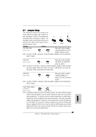
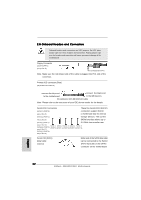
D. MIC_RET and OUT_RET are for HD audio panel only. You don't need to connect them for AC'97 audio panel. E. To activate the front mic. For Windows® XP / XP 64-bit OS: Select "Mixer". Select "Recorder". Then click "FrontMic". For Windows® 7 / 7 64-bit / VistaTM / VistaTM 64-bit OS: Go to the "FrontMic" Tab in the Realtek Control panel. Adjust "Recording Volume". System Panel Header (9-pin PANEL1) (see p.2 No. 21) This header accommodates several system front panel functions. Chassis Speaker Header (4-pin SPEAKER 1) (see p.2 No. 22) Please connect the chassis speaker to this header. Chassis and Power Fan Connectors (3-pin CHA_FAN1) (see p.2 No. 12) (3-pin PWR_FAN1) (see p.2 No. 33) Please connect the fan cables to the fan connectors and match the black wire to the CPU Fan Connector 1 (4-pin CPU_FAN1) 2 3 (see p.2 No. 2) 4 Please connect the CPU fan cable to this connector and match the black wire to the ground pin. Though this motherboard provides 4-Pin CPU fan (Quiet Fan) support, the 3-Pin CPU fan still can work successfully even without the fan speed control function. If you plan to connect the 3-Pin CPU fan to the CPU fan connector on this motherboard, please connect it to Pin 1-3. Pin 1-3 Connected 3-Pin Fan Installation ATX Power Connector (24-pin ATXPWR1) (see p.2 No. 8) 12 24 Please connect an ATX power supply to this connector. 1 13 24 ASRock 890GMH/USB3 Motherboard English
-
 1
1 -
2
-
3
-
4
-
5
-
6
-
7
-
8
-
9
-
10
-
11
-
12
-
13
-
14
-
15
-
16
-
17
-
18
-
 19
19 -
 20
20 -
 21
21 -
 22
22 -
 23
23 -
 24
24 -
 25
25 -
 26
26 -
 27
27 -
 28
28 -
 29
29 -
30
-
31
-
32
-
33
-
34
-
35
-
36
-
37
-
38
-
39
-
40
-
41
-
42
-
43
-
44
-
45
-
46
-
47
-
48
-
49
-
50
-
51
-
52
-
53
-
54
-
55
-
56
-
57
-
58
-
59
-
60
-
61
-
62
-
63
-
64
-
65
-
66
-
67
-
68
-
69
-
70
-
71
-
72
-
73
-
74
-
75
-
76
-
77
-
78
-
79
 |
 |