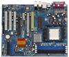
ASRock 939Dual-VSTA User Manual - Page 18
Installing an expansion card
 |
View all ASRock 939Dual-VSTA manuals
Add to My Manuals
Save this manual to your list of manuals |
Page 18 highlights
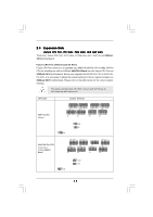
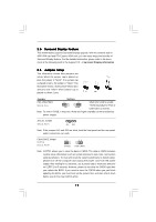
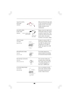
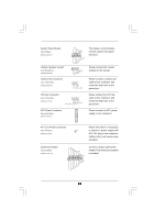
NOTE When adjusting the jumper settings, you may use the tool, Jumper Cap Remover, to help you removing the jumper caps more easily. This Jumper Cap Remover is bundled in your motherboard package, and please follow the "Jumper Cap Remover Instruction" to use it properly. PCI Slots: PCI slots are used to install expansion cards that have the 32-bit PCI interface. PCIE Slots: PCIE1 (PCIE x16 slot) is used for PCI Express cards with x16 lane width graphics cards. For the information of the compatible PCI Express VGA cards, please refer to the "Supported ATi X300 and X300SE Series PCI Express VGA Card List for PCI Express Slot (PCI Express x16)" on page 10. PCIE2 (PCIE x1 slot) is used for PCI Express cards with x1 lane width graphics cards, such as Gigabit LAN card, SATA2 card, etc. AGP slot: The AGP slot is used to install a graphics card. The ASRock AGP slot has a special design of clasp that can securely fasten the inserted graphics card. Please do NOT use a 3.3V AGP card on the AGP slot of this motherboard! It may cause permanent damage! For the voltage information of your AGP card, please check with the AGP card vendors. Installing an expansion card Step 1. Before installing the expansion card, please make sure that the power supply is switched off or the power cord is unplugged. Please read the documentation of the expansion card and make necessary hardware settings for the card before you start the installation. Step 2. Remove the system unit cover (if your motherboard is already installed in a chassis). Step 3. Remove the bracket facing the slot that you intend to use. Keep the screws for later use. Step 4. Align the card connector with the slot and press firmly until the card is completely seated on the slot. Step 5. Fasten the card to the chassis with screws. Step 6. Replace the system cover. 18
-
 1
1 -
2
-
3
-
4
-
5
-
6
-
7
-
8
-
9
-
10
-
11
-
12
-
 13
13 -
 14
14 -
 15
15 -
 16
16 -
 17
17 -
 18
18 -
 19
19 -
 20
20 -
 21
21 -
 22
22 -
 23
23 -
24
-
25
-
26
-
27
-
28
-
29
-
30
-
31
-
32
-
33
-
34
-
35
-
36
-
37
-
38
-
39
-
40
-
41
-
42
-
43
-
44
-
45
 |
 |