ASRock A320M-HDVP User Manual
ASRock A320M-HDVP Manual
 |
View all ASRock A320M-HDVP manuals
Add to My Manuals
Save this manual to your list of manuals |
ASRock A320M-HDVP manual content summary:
- ASRock A320M-HDVP | User Manual - Page 1
- ASRock A320M-HDVP | User Manual - Page 2
documentation are furnished for informational use only and subject to change without notice, and should not be constructed as a commitment by ASRock. ASRock assumes no responsibility for any errors or omissions that may appear in this documentation. With respect to the contents of this documentation - ASRock A320M-HDVP | User Manual - Page 3
if the goods fail to be of acceptable quality and the failure does not amount to a major failure. If you require assistance please call ASRock Tel : +886-2-28965588 ext.123 (Standard International call charges apply) The terms HDMI® and HDMI High-Definition Multimedia Interface, and the HDMI logo - ASRock A320M-HDVP | User Manual - Page 4
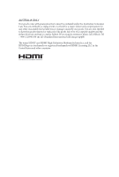
) 25 2.5 Jumpers Setup 26 2.6 Onboard Headers and Connectors 27 2.7 M.2_SSD (NGFF) Module Installation Guide 31 Chapter 3 Software and Utilities Operation 35 3.1 Installing Drivers 35 3.2 ASRock Live Update & APP Shop 36 3.2.1 UI Overview 36 3.2.2 Apps 37 3.2.3 BIOS & Drivers 40 - ASRock A320M-HDVP | User Manual - Page 5
4.1.2 Navigation Keys 43 4.2 Main Screen 44 4.3 OC Tweaker Screen 45 4.4 Advanced Screen 47 4.4.1 CPU Configuration 48 4.4.2 Onboard Devices Configuration 49 4.4.3 Storage Configuration 50 4.4.4 Super IO Configuration 51 4.4.5 ACPI Configuration 52 4.4.6 Trusted Computing 53 - ASRock A320M-HDVP | User Manual - Page 6
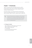
latest VGA cards and CPU support list on ASRock's website as well. ASRock website http://www.asrock.com. 1.1 Package Contents • ASRock A320M-HDVP Motherboard (Micro ATX Form Factor) • ASRock A320M-HDVP Quick Installation Guide • ASRock A320M-HDVP Support CD • 1 x I/O Panel Shield • 2 x Serial ATA - ASRock A320M-HDVP | User Manual - Page 7
DDR4 2400/2133 nonECC, un-buffered memory* * For Ryzen Series CPUs (Picasso and Raven Ridge), ECC is only supported with PRO CPUs. * Please refer to Memory Support List on ASRock's website for more information. (http://www.asrock.com/) * Please refer to page 21 for DDR4 UDIMM maximum frequency - ASRock A320M-HDVP | User Manual - Page 8
A320M-HDVP Expansion Slot AMD Ryzen series CPUs (Matisse, Summit Ridge and Pinnacle Ridge) • 1 x PCI (PCIE2: x8 mode)* AMD Athlon series CPUs • 1 x PCI Express 3.0 x16 Slot (PCIE2: x4 mode)* * Supports NVMe SSD as boot disks • 2 x PCI Express 2.0 x1 Slots • 1 x PCI Slot Graphics • Integrated AMD - ASRock A320M-HDVP | User Manual - Page 9
(32 Gb/s) (with Matisse, Picasso, Summit Ridge, Raven Ridge and Pinnacle Ridge) or Gen3 x2 (16 Gb/s) (with A-Series APU and Athlon 2xxGE series APU)* * Supports NVMe SSD as boot disks * Supports ASRock U.2 Kit English 4 - ASRock A320M-HDVP | User Manual - Page 10
A320M-HDVP Connector • 1 x Print Port Header • 1 x COM Port Header • 1 x SPI TPM Header • 1 x Chassis Intrusion and Speaker Header • 1 x CPU Fan Connector (4-pin) * The CPU Fan Connector supports the CPU fan of maximum 1A (12W) fan power. • 2 x Chassis Fan Connectors (4-pin) * The Chassis Fan - ASRock A320M-HDVP | User Manual - Page 11
* For detailed product information, please visit our website: http://www.asrock.com Please realize that there is a certain risk involved with overclocking, including adjusting the setting in the BIOS, applying Untied Overclocking Technology, or using thirdparty - ASRock A320M-HDVP | User Manual - Page 12
PS2 Mouse PS2 Keyboard 1.3 Motherboard Layout 1 ATX12V A320M-HDVP 2 3 CPU_FAN1 DVI1 VGA A320M-HDVP DDR4_A1 (64 bit, 288-FpinSBmo8d0ul0e) DDR4_A2 (64 bit, 288-pin module) ATXPWR1 SOCKET AM4 COM1 HDMI1 4 USB 3.1 Gen1 USB1 USB2 USB3 USB4 RJ-45 LAN - ASRock A320M-HDVP | User Manual - Page 13
No. Description 1 ATX 12V Power Connector (ATX12V1) 2 CPU Fan Connector (CPU_FAN1) 3 2 x 288-pin DDR4 DIMM Slots (DDR4_A1, DDR4_A2) 4 ATX Power Connector (ATXPWR1) 5 USB 3.2 Gen1 Header (USB3_5_6) 6 USB 2.0 Header (USB_3_4) 7 USB 2.0 Header (USB_5_6) 8 SATA3 Connector (SATA3_3) 9 SATA3 Connector ( - ASRock A320M-HDVP | User Manual - Page 14
1.4 I/O Panel 1 2 3 A320M-HDVP 5 4 6 12 11 No. Description 1 PS/2 Mouse Port 2 D-Sub Port 3 COM Port 4 LAN RJ-45 Port* 5 Line In (Light Blue) 6 Front Speaker (Lime) 10 9 8 7 No. Description 7 - ASRock A320M-HDVP | User Manual - Page 15
Chapter 2 Installation This is a Micro ATX form factor motherboard. Before you install the motherboard, study the configuration of your chassis to ensure that the motherboard fits into it. Pre-installation Precautions Take note of the following precautions before you install motherboard components - ASRock A320M-HDVP | User Manual - Page 16
2.1 Installing the CPU Unplug all power cables before installing the CPU. 1 A320M-HDVP 2 English 11 - ASRock A320M-HDVP | User Manual - Page 17
3 12 English - ASRock A320M-HDVP | User Manual - Page 18
A320M-HDVP 2.2 Installing the CPU Fan and Heatsink After you install the CPU into this motherboard, it is necessary to install a larger heatsink and cooling fan to - ASRock A320M-HDVP | User Manual - Page 19
3 4 14 4-pin FAN cable CPU_FAN1 English - ASRock A320M-HDVP | User Manual - Page 20
Installing the AM4 Box Cooler SR2 1 A320M-HDVP 2 English 15 - ASRock A320M-HDVP | User Manual - Page 21
3 16 English - ASRock A320M-HDVP | User Manual - Page 22
A320M-HDVP 4 4-pin FAN cable CPU_FAN1 17 English - ASRock A320M-HDVP | User Manual - Page 23
Installing the AM4 Box Cooler SR3 1 2 18 English - ASRock A320M-HDVP | User Manual - Page 24
A320M-HDVP 3 4 19 English - ASRock A320M-HDVP | User Manual - Page 25
5 4-pin FAN cable CPU_FAN1 6 CPU_FAN1 USB 2.0 Header USB Please note that this connector is the interface to the LED control board on the SR3, it requires the AMD utility "SR3 Settings Software" to control the LED. *The diagram shown here are for reference only. Please refer to page 28 for the - ASRock A320M-HDVP | User Manual - Page 26
A320M-HDVP 2.3 Installing Memory Modules (DIMM) This motherboard provides two 288-pin DDR4 (Double Data Rate 4) DIMM slots, and supports Dual Channel Memory Technology. 1. For dual channel configuration, you always need to install identical (the same brand, speed, size and chip-type) DDR4 DIMM - ASRock A320M-HDVP | User Manual - Page 27
Ryzen Series CPUs (Pinnacle Ridge): UDIMM Memory Slot A1 B1 SR - - SR DR - - DR SR SR DR DR Frequency (Mhz) 2933 2933 2933 2933 2933 2933 Ryzen Series CPUs (Picasso): UDIMM Memory Slot A1 B1 SR - - SR DR - - DR SR SR DR DR Frequency (Mhz) 2933 2933 2667 2667 2933 - ASRock A320M-HDVP | User Manual - Page 28
2667 2933 2667 SR: Single rank DIMM, 1Rx4 or 1Rx8 on DIMM module label DR: Dual rank DIMM, 2Rx4 or 2Rx8 on DIMM module label A320M-HDVP English 23 - ASRock A320M-HDVP | User Manual - Page 29
The DIMM only fits in one correct orientation. It will cause permanent damage to the motherboard and the DIMM if you force the DIMM into the slot at incorrect orientation. 1 2 3 24 English - ASRock A320M-HDVP | User Manual - Page 30
A320M-HDVP 2.4 Expansion Slots (PCI and PCI Express Slots) There is 1 PCI slot and 3 PCI Express slots on the motherboard. Before installing an expansion card, please make - ASRock A320M-HDVP | User Manual - Page 31
2.5 Jumpers Setup The illustration shows how jumpers are setup. When the jumper cap is placed on the pins, the jumper is "Short". If no jumper cap is placed on the pins, the jumper is "Open". Clear CMOS Header (CLRCMOS1) (see p.7, No. 17) 2-pin Jumper Short: Clear CMOS Open: Default CLRCMOS1 - ASRock A320M-HDVP | User Manual - Page 32
A320M-HDVP 2.6 Onboard Headers and Connectors Onboard headers and connectors are NOT jumpers. Do NOT place jumper caps over these headers and connectors. Placing jumper caps over - ASRock A320M-HDVP | User Manual - Page 33
GND DUMMY SATA3_1 SATA3_3 SATA3_2 SATA3_4 Please connect the chassis intrusion and the chassis speaker to this header. These four SATA3 connectors support SATA data cables for internal storage devices with up to 6.0 Gb/s data transfer rate. USB 2.0 Header (9-pin USB_3_4) (see p.7, No. 6) (9-pin - ASRock A320M-HDVP | User Manual - Page 34
A320M-HDVP 1. High Definition Audio supports Jack Sensing, but the panel wire on the chassis must support HDA to function correctly. Please follow the instructions in our manual and chassis manual to install your system. 2. If you use an AC'97 audio panel, please install it to the front panel audio - ASRock A320M-HDVP | User Manual - Page 35
orientation. Serial Port Header (9-pin COM2) (see p.7, No. 15) RRXD1 DDTR#1 DDSR#1 CCTS#1 1 RRI#1 RRTS#1 GND TTXD1 DDCD#1 This COM2 header supports a serial port module. SPI TPM Header (13-pin SPI_TPM_J1) (see p.7, No. 19) SPI_DQ3 +3.3V Dummy CLK SPI_MOSI RST# TPM_PIRQ 1 SPI_TPM_CS# GND RSMRST - ASRock A320M-HDVP | User Manual - Page 36
A320M-HDVP 2.7 M.2_SSD (NGFF) Module Installation Guide The M.2, also known as the Next Generation Form Factor (NGFF), is a small size and versatile card edge connector that aims to replace mPCIe and mSATA. The Ultra M.2 Socket (M2_1) supports SATA3 6.0 Gb/s module and M.2 PCI Express module up to - ASRock A320M-HDVP | User Manual - Page 37
C B A C B A C B A Step 3 Move the standoff based on the module type and length. The standoff is placed at the nut location D by default. Skip Step 3 and 4 and go straight to Step 5 if you are going to use the default nut. Otherwise, release the standoff by hand. Step 4 Peel off the yellow - ASRock A320M-HDVP | User Manual - Page 38
C NUT2 NUT1 A320M-HDVP Step 6 Tighten the screw with a screwdriver to secure the module into place. Please do not overtighten the screw as this might damage the module. English 33 - ASRock A320M-HDVP | User Manual - Page 39
M.2_SSD (NGFF) Module Support List Vendor SanDisk Intel Intel Kingston Samsung ADATA Crucial ezlink Intel Kingston Kingston Color 240G WD GREEN WDS240G1G0B-00RC30 For the latest updates of M.2_SSD (NFGG) module support list, please visit our website for details: http://www.asrock.com English 34 - ASRock A320M-HDVP | User Manual - Page 40
A320M-HDVP Chapter 3 Software and Utilities Operation 3.1 Installing Drivers The Support CD that comes with the motherboard contains necessary drivers and useful utilities that enhance the motherboard's features. Running The Support CD To begin using the support CD, insert the CD into your CD-ROM - ASRock A320M-HDVP | User Manual - Page 41
Live Update & APP Shop is an online store for purchasing and downloading software applications for your ASRock computer. You can quickly and easily install various apps and support utilities.With ASRock Live Update & APP Shop, you can optimize your system and keep your motherboard up to date simply - ASRock A320M-HDVP | User Manual - Page 42
A320M-HDVP 3.2.2 Apps When the "Apps" tab is selected, you will see all the available apps on screen for you to download. Installing an App Step 1 Find - ASRock A320M-HDVP | User Manual - Page 43
Step 3 If you want to install the app, click on the red icon to start downloading. Step 4 When installation completes, you can find the green "Installed" icon appears on the upper right corner. English To uninstall it, simply click on the trash can icon . *The trash icon may not appear for - ASRock A320M-HDVP | User Manual - Page 44
A320M-HDVP Upgrading an App You can only upgrade the apps you have already installed. When there is an available new version for your app, you will - ASRock A320M-HDVP | User Manual - Page 45
3.2.3 BIOS & Drivers Installing BIOS or Drivers When the "BIOS & Drivers" tab is selected, you will see a list of recommended or critical updates for the BIOS or drivers. Please update them all soon. Step 1 Please check the item information before update. Click on Step 2 to see more details. - ASRock A320M-HDVP | User Manual - Page 46
A320M-HDVP 3.2.4 Setting In the "Setting" page, you can change the language, select the server location, and determine if you want to automatically run the ASRock Live Update & APP Shop on Windows startup. 41 English - ASRock A320M-HDVP | User Manual - Page 47
Chapter 4 UEFI SETUP UTILITY 4.1 Introduction This section explains how to use the UEFI SETUP UTILITY to configure your system. You may run the UEFI SETUP UTILITY by pressing or right after you power on the computer, otherwise, the Power-On-Self-Test (POST) will continue with its test - ASRock A320M-HDVP | User Manual - Page 48
A320M-HDVP 4.1.2 Navigation Keys Use < > key or < > key to choose among the selections on the menu bar, and use < > key or < > key to move the cursor up - ASRock A320M-HDVP | User Manual - Page 49
4.2 Main Screen When you enter the UEFI SETUP UTILITY, the Main screen will appear and display the system overview. 44 English - ASRock A320M-HDVP | User Manual - Page 50
OC Tweaker screen, you can set up overclocking features. A320M-HDVP Because the UEFI software is constantly being updated, the following Uncore OC Voltage Specify the SoC/Uncore voltage (VDD_SOC) in mV to support memory and Infinity Fabric overclocking. VDD_SOC also determines the GPU voltage on - ASRock A320M-HDVP | User Manual - Page 51
CLDO VDDP Voltage Control VDDP is a voltage for the DDR4 bus signaling (PHY), and it is dereived from your DRAM voltage (VDDIO_Mem). As a result, VDDP voltage in mV can approach but not exceed your DRAM voltage. CLDO VDDG Voltage Control VDDG represents voltage for the data portion of the Infinity - ASRock A320M-HDVP | User Manual - Page 52
A320M-HDVP 4.4 Advanced Screen In this section, you may set the configurations for Auto] is selected, the resolution will be set to 1920 x 1080 if the monitor supports Full HD resolution. If the monitor does not support Full HD resolution, then the resolution will be set to 1024 x 768. When [Disable - ASRock A320M-HDVP | User Manual - Page 53
4.4.1 CPU Configuration PSS Support This item allows you to enable or disable the generation of ACPI_PPC, _PSS SMT, a power cycle is needed after selecting [Auto]. Warning: S3 is not supported on systems where SMT is disabled. AMD fTPM Switch Use this to enable or disable AMD CPU fTPM. 48 English - ASRock A320M-HDVP | User Manual - Page 54
4.4.2 Onboard Devices Configuration A320M-HDVP SR-IOV Support Enable/disable the SR-IOV (Single Root IO Virtualization Support) if the system has SR-IOV capable PCIe devices. Gnb Hd Audio Enable/disable the support for Gnb Hd Audio. Front Panel Enable/disable front panel HD audio. Restore on AC/ - ASRock A320M-HDVP | User Manual - Page 55
4.4.3 Storage Configuration SATA Mode AHCI: Supports new features that improve performance. RAID: Combine multiple disk drives into a logical unit. SATA Hot Plug Enable/disable the SATA Hot Plug function. 50 English - ASRock A320M-HDVP | User Manual - Page 56
4.4.4 Super IO Configuration A320M-HDVP Serial Port Enable or disable the Serial port. Serial Port Address Select the address of the Serial port. Serial Port Enable or disable the Serial - ASRock A320M-HDVP | User Manual - Page 57
for ACPI S3 power saving. Deep Sleep Configure deep sleep mode for power saving when the computer is shut down. PS/2 Keyboard S4/S5 Wakeup Support Allow the system to be waked up by a PS/2 Keyboard in S4/S5. RTC Alarm Power On Allow the system to be waked up by - ASRock A320M-HDVP | User Manual - Page 58
4.4.6 Trusted Computing A320M-HDVP Security Device Support Enable to activate Trusted Platform Module (TPM) security for your hard disk drives. English 53 - ASRock A320M-HDVP | User Manual - Page 59
4.4.7 AMD CBS The AMD CBS menu accesses AMD specific features. 54 English - ASRock A320M-HDVP | User Manual - Page 60
4.4.8 AMD PBS A320M-HDVP The AMD PBS menu accesses AMD specific features. English 55 - ASRock A320M-HDVP | User Manual - Page 61
4.5 Tools Instant Flash Save UEFI files in your USB storage device and run Instant Flash to update your UEFI. 56 English - ASRock A320M-HDVP | User Manual - Page 62
A320M-HDVP 4.6 Hardware Health Event Monitoring Screen This section allows you to monitor the status of the hardware on your system, including the parameters of the CPU - ASRock A320M-HDVP | User Manual - Page 63
Chassis Fan 2 Temp Source Select a fan temperature source for Chassis Fan 2. Over Temperature Protection When Over Temperature Protection is enabled, the system automatically shuts down when the motherboard is overheated. Case Open Feature Enable or disable Case Open Feature to detect whether the - ASRock A320M-HDVP | User Manual - Page 64
A320M-HDVP 4.7 Security Screen In this section you may set or change the supervisor/user password for the system. You may also clear the user change the settings in the UEFI Setup Utility. Leave it blank and press enter to remove the password. Secure Boot Enable to support Secure Boot. 59 English - ASRock A320M-HDVP | User Manual - Page 65
4.8 Boot Screen This section displays the available devices on your system for you to configure the boot settings and the boot priority. Boot From Onboard LAN Allow the system to be waked up by the onboard LAN. Boot Beep Select whether the Boot Beep should be turned on or off when the system boots - ASRock A320M-HDVP | User Manual - Page 66
A320M-HDVP Fast Boot Fast Boot minimizes your computer's boot time. In fast mode you may not boot from an USB storage device. CSM (Compatibility Support Module) CSM Enable to launch the Compatibility Support Module. Please do not disable unless you're running a WHCK test. Above 4G Decoding Enable or - ASRock A320M-HDVP | User Manual - Page 67
4.9 Exit Screen Save Changes and Exit When you select this option the following message, "Save configuration changes and exit setup?" will pop out. Select [OK] to save changes and exit the UEFI SETUP UTILITY. Discard Changes and Exit When you select this option the following message, "Discard - ASRock A320M-HDVP | User Manual - Page 68
or want to know more about ASRock, you're welcome to visit ASRock's website at http://www.asrock.com; or you may contact your dealer for further information. For technical questions, please submit a support request form at http://www.asrock.com/support/tsd.asp ASRock Incorporation 2F., No.37, Sec - ASRock A320M-HDVP | User Manual - Page 69
Per FCC Part 2 Section 2.1077(a) Responsible Party Name: ASRock Incorporation Address: 13848 Magnolia Ave, Chino, CA91710 Phone/Fax No: +1-909-590-8308/+1-909-590-1026 hereby declares that the product Product Name : Motherboard Model Number : A320M-HDVP Conforms to the following speci cations: FCC - ASRock A320M-HDVP | User Manual - Page 70
EU Declaration of Conformity For the following equipment: Motherboard (Product Name) A320M-HDVP / ASRock (Model Designation / Trade Name) ASRock Incorporation (Manufacturer Name) 2F., No.37, Sec. 2, Jhongyang S. Rd., Beitou District, Taipei City 112, Taiwan (R.O.C.) (Manufacturer Address) ڛ
-
 1
1 -
 2
2 -
 3
3 -
 4
4 -
 5
5 -
 6
6 -
 7
7 -
8
-
9
-
10
-
11
-
12
-
13
-
14
-
15
-
16
-
17
-
18
-
19
-
20
-
21
-
22
-
23
-
24
-
25
-
26
-
27
-
28
-
29
-
30
-
31
-
32
-
33
-
34
-
35
-
36
-
37
-
38
-
39
-
40
-
41
-
42
-
43
-
44
-
45
-
46
-
47
-
48
-
49
-
50
-
51
-
52
-
53
-
54
-
55
-
56
-
57
-
58
-
59
-
60
-
61
-
62
-
63
-
64
-
65
-
66
-
67
-
68
-
69
-
70
 |
 |