ASRock A770DE User Manual - Page 25
Chassis and Power Fan Connectors - cpu support
 |
View all ASRock A770DE manuals
Add to My Manuals
Save this manual to your list of manuals |
Page 25 highlights
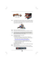
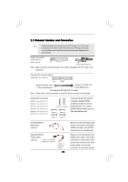
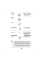
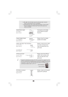
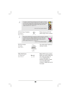
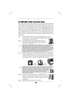
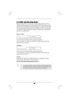
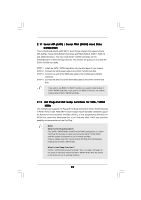
D. MIC_RET and OUT_RET are for HD audio panel only. You don't need to connect them for AC'97 audio panel. E. Enter BIOS Setup Utility. Enter Advanced Settings, and then select Chipset Configuration. Set the Front Panel Control option from [Auto] to [Enabled]. System Panel Header (9-pin PANEL1) (see p.10 No. 23) Chassis Speaker Header (4-pin SPEAKER 1) (see p.10 No. 17) PLED+ PLEDPWRBTN# GND 1 DUMMY RESET# GND HDLEDHDLED+ 1 SPEAKER DUMMY DUMMY +5V Chassis and Power Fan Connectors (3-pin CHA_FAN1) (see p.10 No. 19) GND +12V CHA_FAN_SPEED (3-pin PWR_FAN1) (see p.10 No. 35) PWR_FAN_SPEED +12V GND This header accommodates several system front panel functions. Please connect the chassis speaker to this header. Please connect the fan cables to the fan connectors and match the black wire to the ground pin. CPU Fan Connector (4-pin CPU_FAN1) (see p.10 No. 5) FAN_SPEED_CONTROL 4 CPU_FAN_SPEED 3 +12V 2 GND 1 Please connect the CPU fan cable to this connector and match the black wire to the ground pin. Though this motherboard provides 4-Pin CPU fan (Quiet Fan) support, the 3-Pin CPU fan still can work successfully even without the fan speed control function. If you plan to connect the 3-Pin CPU fan to the CPU fan connector on this motherboard, please connect it to Pin 1-3. Pin 1-3 Connected 3-Pin Fan Installation ATX Power Connector (24-pin ATXPWR1) (see p.10 No. 8) 12 24 1 13 Please connect an ATX power supply to this connector. 25
-
 1
1 -
2
-
3
-
4
-
5
-
6
-
7
-
8
-
9
-
10
-
11
-
12
-
13
-
14
-
15
-
16
-
17
-
18
-
19
-
 20
20 -
 21
21 -
 22
22 -
 23
23 -
 24
24 -
 25
25 -
 26
26 -
 27
27 -
 28
28 -
 29
29 -
 30
30 -
31
-
32
-
33
-
34
-
35
-
36
-
37
-
38
-
39
-
40
-
41
-
42
-
43
-
44
-
45
-
46
-
47
-
48
-
49
-
50
-
51
-
52
-
53
-
54
-
55
-
56
-
57
-
58
-
59
 |
 |