ASRock AB350M User Manual - Page 36
Caution: Never install the RGB, LED cable in the wrong orienta, tion; otherwise, the cable may
 |
View all ASRock AB350M manuals
Add to My Manuals
Save this manual to your list of manuals |
Page 36 highlights
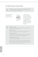
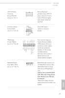
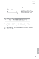
ATX 12V Power Connector (8-pin ATX12V1) (see p.5 or 7, No. 1) Serial Port Header (9-pin COM1) (see p.5 or 7, No. 15) TPM Header (17-pin TPMS1) (see p.5 or 7, No. 16) RGB LED Header (4-pin RGB_LED1) (see p.5 or 7, No. 17) GND SERIRQ # S_PWRDWN # GN D LAD1 LAD2 SMB_DATA_MAIN SMB_CLK_MAIN GN D +3VS B LAD0 +3V LAD3 PCIRST # FRAM E PCICLK AB350M A320M 8 5 This motherboard provides a 8-pin ATX 12V 4 1 power connector. To use a 4-pin ATX power supply, please plug it along Pin 1 and Pin 5. RRXD1 DDTR#1 DDSR#1 CCTS#1 1 RRI#1 RRTS#1 GND TTXD1 DDCD#1 This COM1 header supports a serial port module. GN D This connector supports Trusted Platform Module 1 (TPM) system, which can securely store keys, digital certificates, passwords, and data. A TPM system also helps enhance network security, protects digital identities, and ensures platform integrity. 1 12V G R B RGB LED header is used to connect RGB LED extension cable which allows users to choose from various LED lighting effects. Caution: Never install the RGB LED cable in the wrong orientation; otherwise, the cable may be damaged. *Please refer to page 43 for for further instructions on these two headers. English 31
-
 1
1 -
2
-
3
-
4
-
5
-
6
-
7
-
8
-
9
-
10
-
11
-
12
-
13
-
14
-
15
-
16
-
17
-
18
-
19
-
20
-
21
-
22
-
23
-
24
-
25
-
26
-
27
-
28
-
29
-
30
-
 31
31 -
 32
32 -
 33
33 -
 34
34 -
 35
35 -
 36
36 -
 37
37 -
 38
38 -
 39
39 -
 40
40 -
 41
41 -
42
-
43
-
44
-
45
-
46
-
47
-
48
-
49
-
50
-
51
-
52
-
53
-
54
-
55
-
56
-
57
-
58
-
59
-
60
-
61
-
62
-
63
-
64
-
65
-
66
-
67
-
68
-
69
 |
 |
