ASRock B150M Pro4 User Manual - Page 9
Connector, Feature, Hardware, Monitor - bios
 |
View all ASRock B150M Pro4 manuals
Add to My Manuals
Save this manual to your list of manuals |
Page 9 highlights
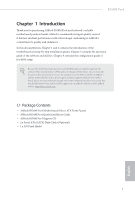
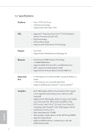
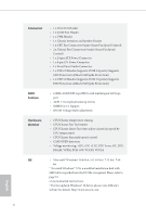
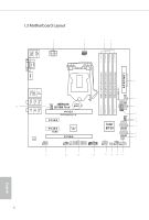
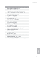
Connector • 1 x Print Port Header • 1 x COM Port Header • 1 x TPM Header • 1 x Chassis Intrusion and Speaker Header • 1 x CPU Fan Connector (4-pin) (Smart Fan Speed Control) • 2 x Chassis Fan Connectors (4-pin) (Smart Fan Speed Control) • 1 x 24 pin ATX Power Connector • 1 x 8 pin 12V Power Connector • 1 x Front Panel Audio Connector • 1 x USB 2.0 Header (Supports 2 USB 2.0 ports) (Supports ESD Protection (ASRock Full Spike Protection)) • 1 x USB 3.0 Header (Supports 2 USB 3.0 ports) (Supports ESD Protection (ASRock Full Spike Protection)) BIOS Feature • 128Mb AMI UEFI Legal BIOS with multilingual GUI sup- port • ACPI 1.1 Compliant wake up events • SMBIOS 2.3.1 Support • DRAM Voltage Multi-adjustment Hardware Monitor • CPU/Chassis temperature sensing • CPU/Chassis Fan Tachometer • CPU/Chassis Quiet Fan (Auto adjust chassis fan speed by CPU temperature) • CPU/Chassis Fan multi-speed control • CASE OPEN detection • Voltage monitoring: +12V, +5V, +3.3V, CPU Vcore, GT_CPU, DRAM, VPPM, PCH 1.0V, VCCIO, VCCSA OS • Microsot® Windows® 10 64-bit / 8.1 64-bit / 7 32-bit / 7 64- bit * To install Windows® 7 OS, a modiied installation disk with xHCI drivers packed into the ISO ile is required. Please refer to page 33 or more detailed instructions. * For the updated Windows® 10 driver, please visit ASRock's website for details: http://www.asrock.com English 4
-
 1
1 -
2
-
3
-
 4
4 -
 5
5 -
 6
6 -
 7
7 -
 8
8 -
 9
9 -
 10
10 -
 11
11 -
 12
12 -
 13
13 -
 14
14 -
15
-
16
-
17
-
18
-
19
-
20
-
21
-
22
-
23
-
24
-
25
-
26
-
27
-
28
-
29
-
30
-
31
-
32
-
33
-
34
-
35
-
36
-
37
-
38
-
39
-
40
-
41
-
42
-
43
-
44
-
45
-
46
-
47
-
48
-
49
-
50
-
51
-
52
-
53
-
54
-
55
-
56
-
57
-
58
-
59
-
60
-
61
-
62
-
63
-
64
-
65
-
66
-
67
-
68
-
69
-
70
-
71
-
72
-
73
-
74
 |
 |