ASRock B550 Pro4 User Manual - Page 33
Power LED and Speaker, USB 3.2 Gen1 Header
 |
View all ASRock B550 Pro4 manuals
Add to My Manuals
Save this manual to your list of manuals |
Page 33 highlights
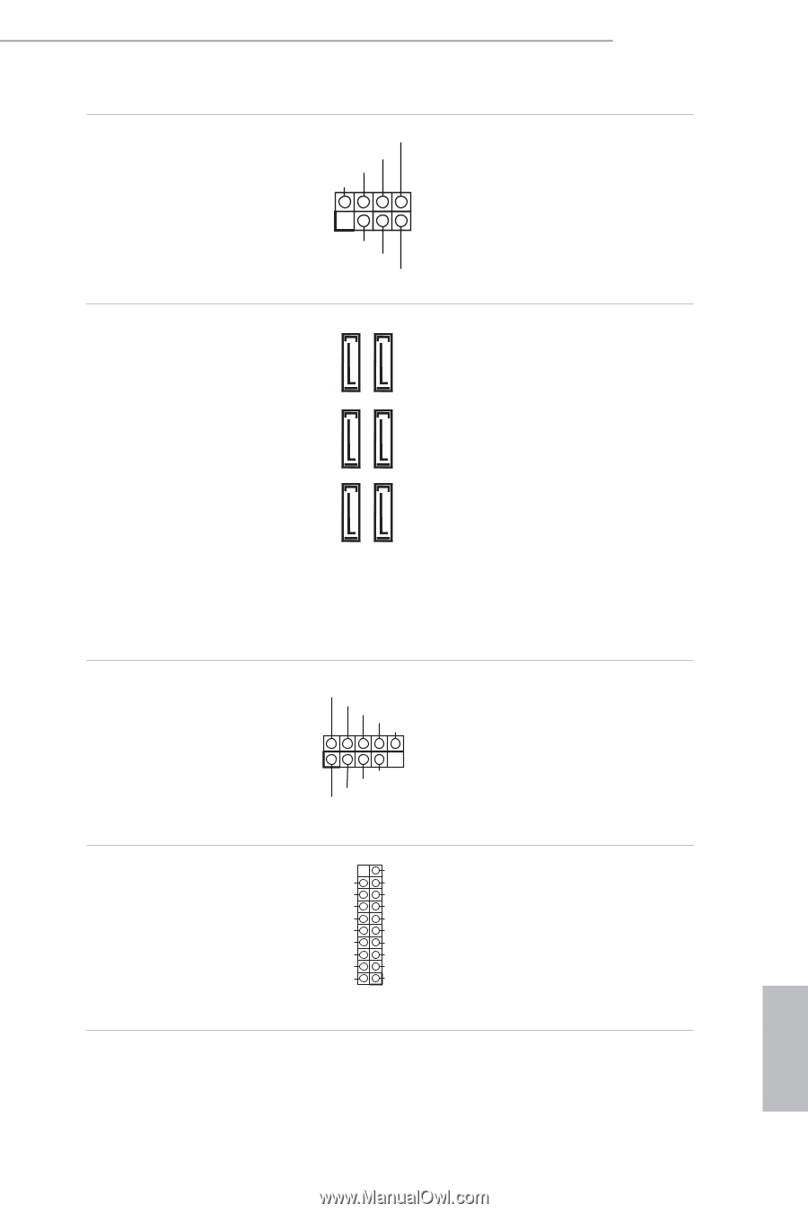
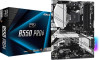
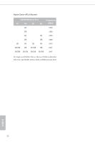
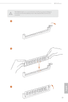
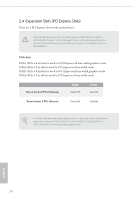
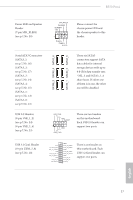
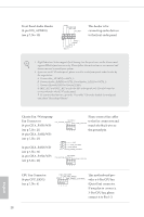
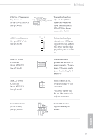
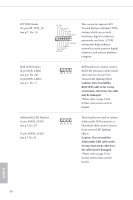
B550 Pro4 Power LED and Speaker Header (7-pin SPK_PLED1) (see p.7, No. 20) Serial ATA3 Connectors (SATA3_1: see p.7, No. 16) (SATA3_2: see p.7, No. 17) (SATA3_3: see p.7, No. 14) (SATA3_4: see p.7, No. 15) (SATA3_5: see p.7, No. 12) (SATA3_6: see p.7, No. 13) USB 2.0 Headers (9-pin USB_1_2) (see p.7, No. 24) (9-pin USB_3_4) (see p.7, No. 23) SATA3_2 SATA3_4 SATA3_6 SATA3_1 SATA3_3 SATA3_5 SPEAKER DUMMY DUMMY +5V 1 PLED+ PLED+ PLED- Please connect the chassis power LED and the chassis speaker to this header. These six SATA3 connectors support SATA data cables for internal storage devices with up to 6.0 Gb/s data transfer rate. * M2_3 and SATA3_5_6 share lanes. If either one of them is in use, the other one will be disabled. USB_PWR PP+ GND DUMMY 1 GND P+ PUSB_PWR There are two headers on this motherboard. Each USB 2.0 header can support two ports. USB 3.2 Gen1 Header (19-pin USB3_7_8) (see p.7, No. 10) Vbus IntA_PA_SSRXIntA_PA_SSRX+ GND IntA_PA_SSTXIntA_PA_SSTX+ GND IntA_PA_DIntA_PA_D+ Vbus IntA_PB_SSRXIntA_PB_SSRX+ GND IntA_PB_SSTXIntA_PB_SSTX+ GND IntA_PB_DIntA_PB_D+ Dummy 1 There is one header on this motherboard. Each USB 3.2 Gen1 header can support two ports. English 27
-
 1
1 -
2
-
3
-
4
-
5
-
6
-
7
-
8
-
9
-
10
-
11
-
12
-
13
-
14
-
15
-
16
-
17
-
18
-
19
-
20
-
21
-
22
-
23
-
24
-
25
-
26
-
27
-
 28
28 -
 29
29 -
 30
30 -
 31
31 -
 32
32 -
 33
33 -
 34
34 -
 35
35 -
 36
36 -
 37
37 -
 38
38 -
39
-
40
-
41
-
42
-
43
-
44
-
45
-
46
-
47
-
48
-
49
-
50
-
51
-
52
-
53
-
54
-
55
-
56
-
57
-
58
-
59
-
60
-
61
-
62
-
63
-
64
-
65
-
66
-
67
-
68
-
69
-
70
-
71
-
72
-
73
-
74
-
75
-
76
-
77
-
78
-
79
-
80
-
81
-
82
-
83
-
84
-
85
-
86
-
87
-
88
-
89
-
90
-
91
 |
 |