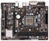
ASRock B75M-DGS R2.0 User Manual - Page 29
Please connect an ATX 12V
 |
View all ASRock B75M-DGS R2.0 manuals
Add to My Manuals
Save this manual to your list of manuals |
Page 29 highlights
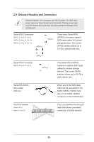
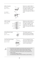
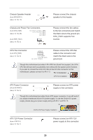
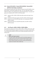
Chassis Speaker Header (4-pin SPEAKER 1) (see p.14, No. 16) Chassis and Power Fan Connectors (4-pin CHA_FAN1) FAN_SPEED_CONTROL CHA_FAN_SPEED (see p.14, No. 26) +12V GND (3-pin PWR_FAN1) (see p.14, No. 2) Please connect the chassis speaker to this header. Please connect the fan cables to the fan connectors and match the black wire to the ground pin. CHA_FAN1 supports Fan Control. CPU Fan Connector (4-pin CPU_FAN1) 4 3 2 1 (see p.14, No. 5) GND +12V CPU_FAN_SPEED FAN_SPEED_CONTROL Please connect the CPU fan cable to the connector and match the black wire to the ground pin. Though this motherboard provides 4-Pin CPU fan (Quiet Fan) support, the 3-Pin CPU fan still can work successfully even without the fan speed control function. If you plan to connect the 3-Pin CPU fan to the CPU fan connector on this motherboard, please connect it to Pin 1-3. Pin 1-3 Connected 3-Pin Fan Installation ATX Power Connector 24 (24-pin ATXPWR1) (see p.14, No. 3) 12 Please connect an ATX power 13 supply to this connector. 1 Though this motherboard provides 24-pin ATX power connector, it can still work if you adopt a traditional 20-pin ATX power supply. To use the 20-pin ATX power supply, please plug your power supply along with Pin 1 and Pin 13. 24 13 20-Pin ATX Power Supply Installation 12 1 ATX 12V Power Connector (4-pin ATX12V1) (see p.14, No. 1) Please connect an ATX 12V power supply to this connector. 29
-
 1
1 -
2
-
3
-
4
-
5
-
6
-
7
-
8
-
9
-
10
-
11
-
12
-
13
-
14
-
15
-
16
-
17
-
18
-
19
-
20
-
21
-
22
-
23
-
 24
24 -
 25
25 -
 26
26 -
 27
27 -
 28
28 -
 29
29 -
 30
30 -
 31
31 -
 32
32 -
 33
33 -
 34
34 -
35
-
36
-
37
-
38
-
39
-
40
-
41
-
42
-
43
-
44
-
45
-
46
-
47
-
48
-
49
-
50
-
51
-
52
-
53
-
54
-
55
-
56
-
57
-
58
-
59
-
60
-
61
-
62
 |
 |
