ASRock B75M-GL User Manual - Page 31
Consumer Infrared Module Header
 |
View all ASRock B75M-GL manuals
Add to My Manuals
Save this manual to your list of manuals |
Page 31 highlights
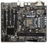
USB 2.0 Headers (9-pin USB6_7) (see p.12, No. 18) (9-pin USB8_9) (see p.12, No. 19) USB_PWR P-9 P+9 GND DUMMY 1 GND P+8 P-8 USB_PWR Infrared Module Header (5-pin IR1) (see p.12, No. 21) Besides two default USB 2.0 ports on the I/O panel, there are two USB 2.0 headers on this motherboard. Each USB 2.0 header can support two USB 2.0 ports. This header supports an optional wireless transmitting and receiving infrared module. Consumer Infrared Module Header (4-pin CIR1) (see p.12, No. 20) This header can be used to connect the remote controller receiver. Front Panel Audio Header (9-pin HD_AUDIO1) (see p.12, No. 28) This is an interface for front panel audio cable that allows convenient connection and control of audio devices. 1. High Definition Audio supports Jack Sensing, but the panel wire on the chassis must support HDA to function correctly. Please follow the instructions in our manual and chassis manual to install your system. 2. If you use an AC'97 audio panel, please install it to the front panel audio header by the steps below: A. Connect Mic_IN (MIC) to MIC2_L. B. Connect Audio_R (RIN) to OUT2_R and Audio_L (LIN) to OUT2_L. C. Connect Ground (GND) to Ground (GND). D. MIC_RET and OUT_RET are for HD audio panel only. You don't need to connect them for AC'97 audio panel. 31
-
 1
1 -
2
-
3
-
4
-
5
-
6
-
7
-
8
-
9
-
10
-
11
-
12
-
13
-
14
-
15
-
16
-
17
-
18
-
19
-
20
-
21
-
22
-
23
-
24
-
25
-
 26
26 -
 27
27 -
 28
28 -
 29
29 -
 30
30 -
 31
31 -
 32
32 -
 33
33 -
 34
34 -
 35
35 -
 36
36 -
37
-
38
-
39
-
40
-
41
-
42
-
43
-
44
-
45
-
46
-
47
-
48
-
49
-
50
-
51
-
52
-
53
-
54
-
55
-
56
-
57
-
58
-
59
-
60
-
61
-
62
-
63
 |
 |
