ASRock B85 Anniversary User Manual - Page 27
A´X Power Connector, A´X 12V Power
 |
View all ASRock B85 Anniversary manuals
Add to My Manuals
Save this manual to your list of manuals |
Page 27 highlights
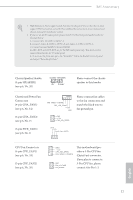
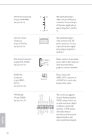
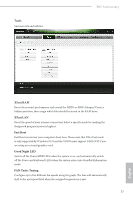
ATX Power Connector (24-pin ATXPWR1) (see p.6, No. 5) ATX 12V Power Connector (8-pin ATX12V1) (see p.6, No. 2) 12 24 1 13 8 5 4 1 PCIe Power Connector (4-pin PCIE_PWR1) (see p.6, No. 25) SPDIF Out Connector (2-pin SPDIF_ OUT1) (see p.6, No. 22) TPM Header (17-pin TPMS1) (see p.6, No. 19) 1 GND SPDIFOUT 1 PCICLK FRAME PCIRST# LAD3 +3V LAD0 +3VSB GND GND SMB_CLK_MAIN SMB_DATA_MAIN LAD2 LAD1 GND S_PWRDWN# SERIRQ# GND his motherboard provides a 24-pin ATX power connector. To use a 20-pin ATX power supply, please plug it along Pin 1 and Pin 13. his motherboard provides an 8-pin ATX 12V power connector. To use a 4-pin ATX power supply, please plug it along Pin 1 and Pin 5. Please connect a 4 pin molex power cable to this connector when more than three graphics cards are installed. Please connect the SPDIF_OUT connector of a HDMI VGA card to this header with a cable. his connector supports Trusted Platform Module (TPM) system, which can securely store keys, digital certiicates, passwords, and data. A TPM system also helps enhance network security, protects digital identities, and ensures platform integrity. English 22
-
 1
1 -
2
-
3
-
4
-
5
-
6
-
7
-
8
-
9
-
10
-
11
-
12
-
13
-
14
-
15
-
16
-
17
-
18
-
19
-
20
-
21
-
 22
22 -
 23
23 -
 24
24 -
 25
25 -
 26
26 -
 27
27 -
 28
28 -
 29
29 -
 30
30 -
 31
31 -
 32
32 -
33
-
34
-
35
-
36
-
37
-
38
-
39
-
40
-
41
-
42
-
43
-
44
-
45
-
46
-
47
-
48
-
49
-
50
-
51
-
52
-
53
-
54
-
55
-
56
-
57
-
58
-
59
-
60
-
61
-
62
-
63
-
64
-
65
-
66
-
67
-
68
-
69
-
70
-
71
-
72
-
73
-
74
-
75
-
76
-
77
-
78
-
79
-
80
-
81
-
82
-
83
-
84
-
85
-
86
-
87
-
88
-
89
-
90
-
91
-
92
-
93
-
94
-
95
-
96
-
97
 |
 |
