ASRock ConRoe1333-D667 R1.0 User Manual - Page 21
ATX Power Connector - windows 7
 |
View all ASRock ConRoe1333-D667 R1.0 manuals
Add to My Manuals
Save this manual to your list of manuals |
Page 21 highlights
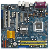
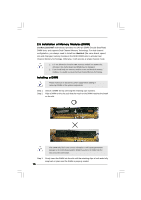
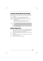
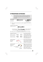
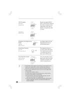
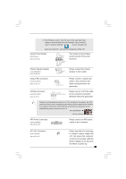
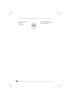
F. Enter Windows system. Click the icon on the lower right hand taskbar to enter Realtek HD Audio Manager. Click "Audio I/O", select "Connector Settings" , choose "Disable front panel jack detection", and save the change by clicking "OK". System Panel Header (9-pin PANEL1) (see p.10 No. 13) Chassis Speaker Header (4-pin SPEAKER 1) (see p.10 No. 15) PLED+ PLEDPWRBTN# GND 1 DUMMY RESET# GND HDLEDHDLED+ 1 SPEAKER DUMMY DUMMY +5V This header accommodates several system front panel functions. Please connect the chassis speaker to this header. Chassis Fan Connector (3-pin CHA_FAN1) (see p.10 No. 16) GND +12V CHA_FAN_SPEED Please connect a chassis fan cable to this connector and match the black wire to the ground pin. CPU Fan Connector (4-pin CPU_FAN1) (see p.10 No. 3) +12V CPU_FAN_SPEED GND FAN_SPEED_CONTROL 1 2 3 4 Please connect a CPU fan cable to this connector and match the black wire to the ground pin. Though this motherboard provides 4-Pin CPU fan (Quiet Fan) support, the 3-Pin CPU fan still can work successfully even without the fan speed control function. If you plan to connect the 3-Pin CPU fan to the CPU fan connector on this motherboard, please connect it to Pin 1-3. Pin 1-3 Connected 3-Pin Fan Installation ATX Power Connector (20-pin ATXPWR1) (see p.10 No. 26) Please connect an ATX power supply to this connector. ATX 12V Connector (4-pin ATX12V1) (see p.10 No. 2) Please note that it is necessary to connect a power supply with ATX 12V plug to this connector so that it can provides sufficient power. Failing to do so will cause the failure to power up. 21
-
 1
1 -
2
-
3
-
4
-
5
-
6
-
7
-
8
-
9
-
10
-
11
-
12
-
13
-
14
-
15
-
 16
16 -
 17
17 -
 18
18 -
 19
19 -
 20
20 -
 21
21 -
 22
22 -
 23
23 -
 24
24 -
 25
25 -
 26
26 -
27
-
28
-
29
-
30
-
31
-
32
-
33
-
34
-
35
-
36
-
37
-
38
-
39
-
40
-
41
-
42
 |
 |