ASRock D1800B-ITX Quick Installation Guide - Page 18
Platform Module TPM system
 |
View all ASRock D1800B-ITX manuals
Add to My Manuals
Save this manual to your list of manuals |
Page 18 highlights
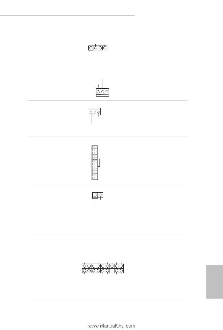
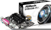
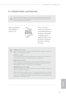
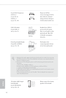
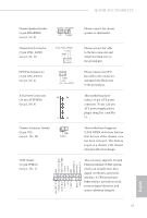
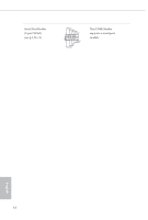
Q1900B-ITX/D1800B-ITX Chassis Speaker Header (4-pin SPEAKER1) (see p.1, No. 6) DUMMY SPEAKER 1 +5V DUMMY Chassis Fan Connector (3-pin CHA_FAN1) (see p.1, No. 11) CHA_ FAN_SPEED + 12V GND CPU Fan Connectors (3-pin CPU_FAN1) (see p.1, No. 2) GND +12V CPU_FAN_SPEED ATX Power Connector (24-pin ATXPWR1) (see p.1, No. 4) 12 24 1 13 Chassis Intrusion Header (2-pin CI1) (see p.1, No. 12) 1 GND Signal TPM Header (17-pin TPMS1) (see p.1, No. 1) 1 F_CLKRUN# SERIRQ# S_PWRDWN# GND LAD1_L LAD2_L SMB_DATA_MAIN SMB_CLK_MAIN GND Please connect the chassis speaker to this header. Please connect fan cable to the fan connector and match the black wire to the ground pin. Please connect the CPU fan cable to the connector and match the black wire to the ground pin. This motherboard provides a 24-pin ATX power connector. To use a 20-pin ATX power supply, please plug it along Pin 1 and Pin 13. This motherboard supports CASE OPEN detection feature that detects if the chassis cove has been removed. This feature requires a chassis with chassis intrusion detection design. This connector supports Trusted Platform Module (TPM) system, which can securely store keys, digital certificates, passwords, and data. A TPM system also helps enhance network security, protects digital identities, and ensures platform integrity. GND +3VSB LAD0_L +3V LAD3_L TPM_RST# LFRAME#_L CK_33M_TPM 17 English
-
 1
1 -
2
-
3
-
4
-
5
-
6
-
7
-
8
-
9
-
10
-
11
-
12
-
 13
13 -
 14
14 -
 15
15 -
 16
16 -
 17
17 -
 18
18 -
 19
19 -
 20
20 -
 21
21 -
 22
22 -
 23
23 -
24
-
25
-
26
-
27
-
28
-
29
-
30
-
31
-
32
-
33
-
34
-
35
-
36
-
37
-
38
-
39
-
40
-
41
-
42
-
43
-
44
-
45
-
46
-
47
-
48
-
49
-
50
-
51
-
52
-
53
-
54
-
55
-
56
-
57
-
58
-
59
-
60
-
61
-
62
-
63
-
64
-
65
-
66
-
67
-
68
-
69
-
70
-
71
-
72
-
73
-
74
-
75
-
76
-
77
-
78
-
79
-
80
-
81
-
82
-
83
-
84
-
85
-
86
-
87
-
88
-
89
-
90
-
91
-
92
-
93
-
94
-
95
-
96
-
97
-
98
-
99
-
100
-
101
-
102
-
103
-
104
-
105
-
106
-
107
-
108
-
109
-
110
-
111
-
112
-
113
-
114
-
115
-
116
-
117
-
118
-
119
-
120
-
121
-
122
-
123
-
124
 |
 |