ASRock FM2A58 Pro User Manual - Page 28
Chassis Fan Connectors, Chassis Speaker Header
 |
View all ASRock FM2A58 Pro manuals
Add to My Manuals
Save this manual to your list of manuals |
Page 28 highlights
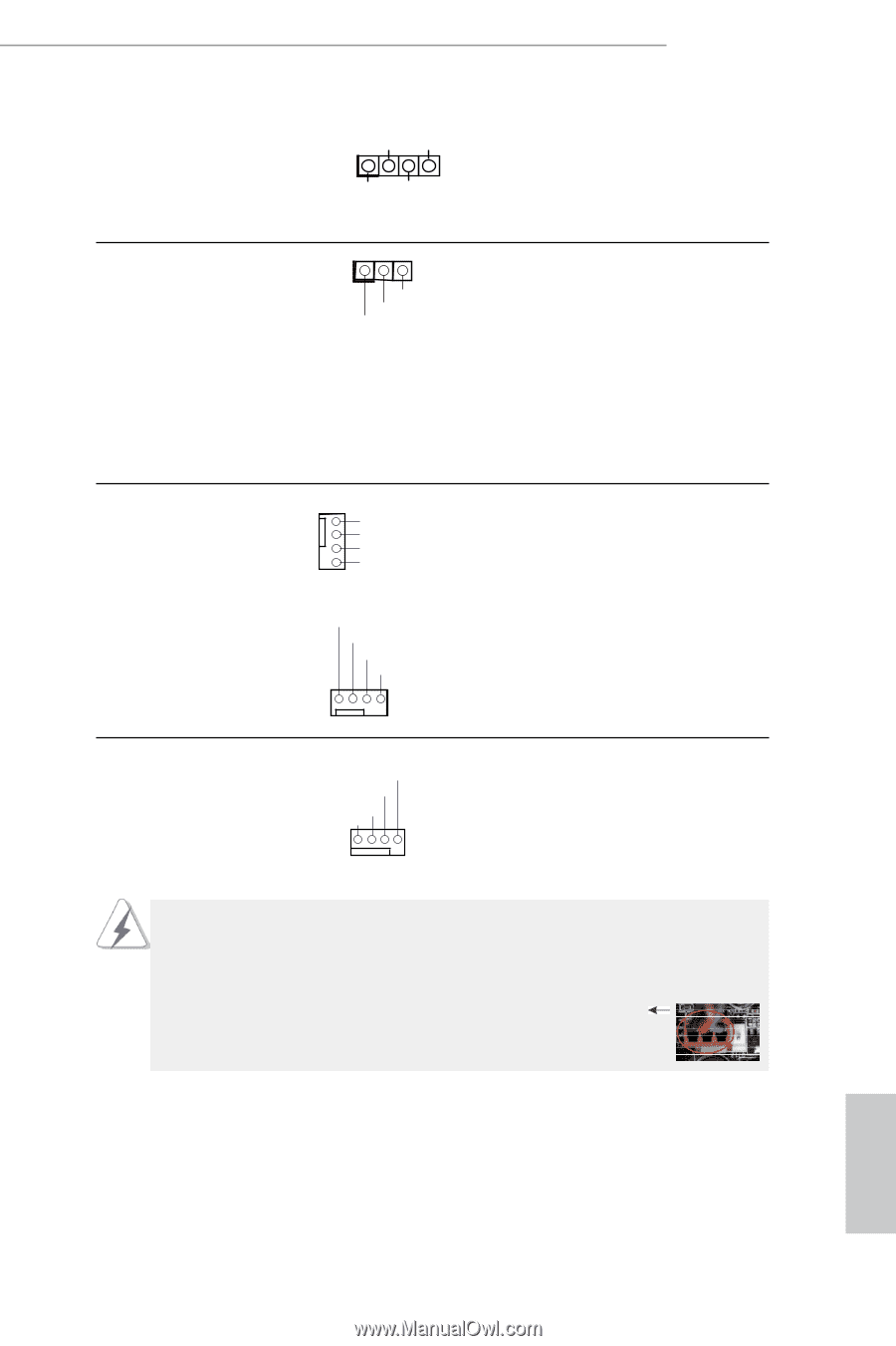
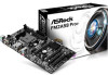
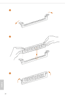
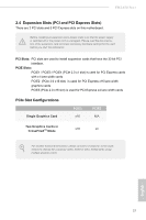
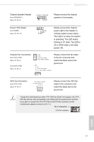
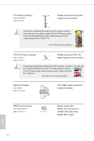
FM2A58 Pro+ Chassis Speaker Header (4-pin SPEAKER 1) (see p.10 No. 9) DUMMY SPEAKER 1 +5V DUMMY Please connect the chassis speaker to this header. Power LED Header (3-pin PLED1) (see p.10 No. 12 1 PLED- PLED+ PLED+ Please connect the chassis power LED to this header to indicate system power status. The LED is on when the system is operating. The LED keeps blinking in S1 state. The LED is off in S3/S4 state or S5 state (power off). Chassis Fan Connectors (4-pin CHA_FAN1) (see p.10 No. 8) GND +12V CHA_FAN_SPEED FAN_SPEED_CONTROL (4-pin CHA_FAN2) GND +12V (see p.10 No. 3) CHA_FAN_SPEED FAN_SPEED_CONTROL Please connect the fan cable to the fan connector and match the black wire to the ground pin. CPU Fan Connector FAN_SPEED_CONTROL (4-pin CPU_FAN1) CPU_FAN_SPEED +12V (see p.10 No. 2) GND 1 2 3 4 Please connect the CPU fan cable to the connector and match the black wire to the ground pin. Though this motherboard provides 4-Pin CPU fan (Quiet Fan) support, the 3-Pin CPU fan still can work successfully even without the fan speed control function. If you plan to connect the 3-Pin CPU fan to the CPU fan connector on this motherboard, please connect it to Pin 1-3. Pin 1-3 Connected 3-Pin Fan Installation English 23
-
 1
1 -
2
-
3
-
4
-
5
-
6
-
7
-
8
-
9
-
10
-
11
-
12
-
13
-
14
-
15
-
16
-
17
-
18
-
19
-
20
-
21
-
22
-
 23
23 -
 24
24 -
 25
25 -
 26
26 -
 27
27 -
 28
28 -
 29
29 -
 30
30 -
 31
31 -
 32
32 -
 33
33 -
34
-
35
-
36
-
37
-
38
-
39
-
40
-
41
-
42
-
43
-
44
-
45
-
46
-
47
-
48
-
49
-
50
-
51
-
52
-
53
-
54
-
55
-
56
-
57
-
58
-
59
-
60
-
61
-
62
-
63
-
64
-
65
 |
 |