ASRock FM2A88M BTC User Manual - Page 27
Chassis and Power Fan, Chassis Speaker Header
 |
View all ASRock FM2A88M BTC manuals
Add to My Manuals
Save this manual to your list of manuals |
Page 27 highlights
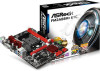
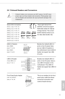
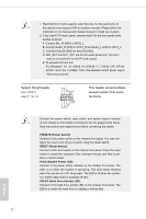
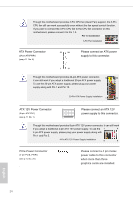
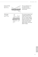
FM2A88M+ BTC The front panel design may differ by chassis. A front panel module mainly consists of power switch, reset switch, power LED, hard drive activity LED, speaker and etc. When connecting your chassis front panel module to this header, make sure the wire assignments and the pin assign-ments are matched correctly. Chassis Speaker Header (4-pin SPEAKER 1) (see p.11 No. 12) Front_RFront_R+ Front_L+ Front_L1 Please connect the chassis speaker to this header. Chassis and Power Fan Connectors (3-pin CHA_FAN1) (see p.11 No. 10) GND +12V CHA_FAN_SPEED FAN_SPEED_CONTROL Please connect the fan cable to the fan connector and match the black wire to the ground pin. (3-pin CHA_FAN2) (see p.11 No. 26) GND + 12V CHA_ FAN_SPEED (3-pin PWR_FAN1) (see p.11 No. 2) CPU Fan Connector FAN_SPEED_CONTROL (4-pin CPU_FAN1) CPU_FAN_SPEED +12V (see p.11 No. 3) GND Please connect the CPU fan cable to the connector and match the black wire to the ground pin. 1 2 3 4 (3-pin CPU_FAN2) (see p.11, No. 4) GND +12V CPU_FAN_SPEED English 23
-
 1
1 -
2
-
3
-
4
-
5
-
6
-
7
-
8
-
9
-
10
-
11
-
12
-
13
-
14
-
15
-
16
-
17
-
18
-
19
-
20
-
21
-
 22
22 -
 23
23 -
 24
24 -
 25
25 -
 26
26 -
 27
27 -
 28
28 -
 29
29 -
 30
30 -
 31
31 -
 32
32 -
33
-
34
-
35
-
36
-
37
-
38
-
39
-
40
-
41
-
42
-
43
-
44
-
45
-
46
-
47
-
48
-
49
-
50
-
51
-
52
-
53
-
54
-
55
-
56
-
57
-
58
-
59
-
60
-
61
 |
 |
