ASRock FM2A88M-DG3 Quick Installation Guide - Page 11
Onboard Headers and Connectors
 |
View all ASRock FM2A88M-DG3 manuals
Add to My Manuals
Save this manual to your list of manuals |
Page 11 highlights
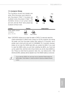
1.4 Onboard Headers and Connectors Onboard headers and connectors are NOT jumpers. Do NOT place jumper caps over these headers and connectors. Placing jumper caps over the headers and connectors will cause permanent damage of the motherboard! Serial ATA3 Connectors (SATA_1: see p.1, No. 10) (SATA_2: see p.1, No. 7) (SATA_3: see p.1, No. 9) (SATA_4: see p.1, No. 8) SATA_1 SATA_2 SATA_3 SATA_4 These four Serial ATA3 (SATA3) connectors support SATA data cables for internal storage devices. The current SATA3 interface allows up to 6.0 Gb/s data transfer rate. USB 2.0 Headers (9-pin USB_7_8) (see p.1 No. 14) (9-pin USB_9_10) (see p.1 No. 13) USB_PWR PP+ GND DUMMY 1 GND P+ PUSB_PWR Besides four default USB 2.0 ports on the I/O panel, there are two USB 2.0 headers on this motherboard. Each USB 2.0 header can support two USB 2.0 ports. USB 3.0 Header (19-pin USB_11_12) (see p.1 No. 6) Vbus IntA_PA_SSRXIntA_PA_SSRX+ GND IntA_PA_SSTXIntA_PA_SSTX+ GND IntA_PA_DIntA_PA_D+ Vbus IntA_PB_SSRXIntA_PB_SSRX+ GND IntA_PB_SSTXIntA_PB_SSTX+ GND IntA_PB_DIntA_PB_D+ Dummy Besides two default USB 3.0 ports on the I/O panel, there is one USB 3.0 header on this motherboard. This USB 3.0 header can support two USB 3.0 ports. Front Panel Audio Header (9-pin HD_AUDIO1) OUT_RET (see p.1 No. 20) MIC_RED PRESENCE# GND This is an interface for the front OUT2_L J_SENSE OUT2_R MIC2_R MIC2_L panel audio cable that allows convenient connection and control of audio devices. 1 English 10
-
 1
1 -
2
-
3
-
4
-
5
-
 6
6 -
 7
7 -
 8
8 -
 9
9 -
 10
10 -
 11
11 -
 12
12 -
 13
13 -
 14
14 -
 15
15 -
 16
16 -
17
-
18
-
19
-
20
 |
 |
