ASRock Fatal1ty B360 Gaming K4 User Manual - Page 32
be damaged., tion; otherwise, the cable may
 |
View all ASRock Fatal1ty B360 Gaming K4 manuals
Add to My Manuals
Save this manual to your list of manuals |
Page 32 highlights
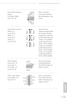
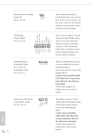
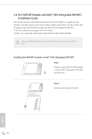
English Chassis Intrusion Header (2-pin CI1) (see p.7, No. 22) 1 GND Signal TPM Header (17-pin TPMS1) (see p.7, No. 21) 1 RGB LED Headers (4-pin RGB_LED1) (see p.7, No. 18) (4-pin RGB_LED2) (see p.7, No. 1) 1 12V G R B Addressable LED Header (3-pin ADDR_LED1) (see p.7, No. 17) 1 GND DO_ADDR VOUT 24 PCICLK FRAM E PCIRST # LAD3 +3V LAD0 +3VS B GN D GN D SMB_CLK_MAIN SMB_DATA_MAIN LAD2 LAD1 GN D S_PWRDWN # SERIRQ # GND This motherboard supports CASE OPEN detection feature that detects if the chassis cove has been removed. This feature requires a chassis with chassis intrusion detection design. This connector supports Trusted Platform Module (TPM) system, which can securely store keys, digital certificates, passwords, and data. A TPM system also helps enhance network security, protects digital identities, and ensures platform integrity. These two RGB headers are used to connect RGB LED extension cable which allows users to choose from various LED lighting effects. Caution: Never install the RGB LED cable in the wrong orientation; otherwise, the cable may be damaged. *Please refer to page 45 for further instructions on this header. This header is used to connect Addressable LED extension cable which allows users to choose from various LED lighting effects. Caution: Never install the Addressable LED cable in the wrong orientation; otherwise, the cable may be damaged. *Please refer to page 46 for further instructions on this header.
-
 1
1 -
2
-
3
-
4
-
5
-
6
-
7
-
8
-
9
-
10
-
11
-
12
-
13
-
14
-
15
-
16
-
17
-
18
-
19
-
20
-
21
-
22
-
23
-
24
-
25
-
26
-
 27
27 -
 28
28 -
 29
29 -
 30
30 -
 31
31 -
 32
32 -
 33
33 -
 34
34 -
 35
35 -
 36
36 -
 37
37 -
38
-
39
-
40
-
41
-
42
-
43
-
44
-
45
-
46
-
47
-
48
-
49
-
50
-
51
-
52
-
53
-
54
-
55
-
56
-
57
-
58
-
59
-
60
-
61
-
62
-
63
-
64
-
65
-
66
-
67
-
68
-
69
-
70
-
71
-
72
-
73
-
74
-
75
-
76
-
77
-
78
-
79
-
80
-
81
-
82
-
83
-
84
-
85
-
86
-
87
-
88
-
89
-
90
-
91
-
92
-
93
-
94
-
95
-
96
 |
 |
