ASRock Fatal1ty H170 Performance User Manual - Page 37
Step 3, Peel off the yellow protective film
 |
View all ASRock Fatal1ty H170 Performance manuals
Add to My Manuals
Save this manual to your list of manuals |
Page 37 highlights
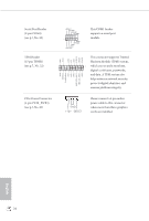
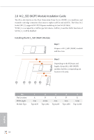
E D C B A E D C B A C B A E D C B A Fatal1ty H170 Performance Series Step 3 Move the standoff based on the module type and length. The standoff is placed at the nut location D by default. Skip Step 3 and 4 and go straight to Step 5 if you are going to use the default nut. Otherwise, release the standoff by hand. Step 4 Peel off the yellow protective film on the nut to be used. Hand tighten the standoff into the desired nut location on the motherboard. Step 5 Align and gently insert the M.2 (NGFF) SSD module into the M.2 slot. Please be aware that the M.2 (NGFF) SSD module only fits in one orientation. English 29
-
 1
1 -
2
-
3
-
4
-
5
-
6
-
7
-
8
-
9
-
10
-
11
-
12
-
13
-
14
-
15
-
16
-
17
-
18
-
19
-
20
-
21
-
22
-
23
-
24
-
25
-
26
-
27
-
28
-
29
-
30
-
31
-
 32
32 -
 33
33 -
 34
34 -
 35
35 -
 36
36 -
 37
37 -
 38
38 -
 39
39 -
 40
40 -
 41
41 -
 42
42 -
43
-
44
-
45
-
46
-
47
-
48
-
49
-
50
-
51
-
52
-
53
-
54
-
55
-
56
-
57
-
58
-
59
-
60
-
61
-
62
-
63
-
64
-
65
-
66
-
67
-
68
-
69
-
70
-
71
-
72
-
73
-
74
-
75
-
76
-
77
-
78
-
79
-
80
-
81
-
82
-
83
-
84
-
85
-
86
-
87
-
88
-
89
-
90
-
91
-
92
-
93
-
94
-
95
 |
 |

29
English
Fatal1ty H170 Performance Series
B
C
D
E
A
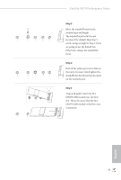
Step 3
Move the standoff based on the
module type and length.
°e standoff is placed at the nut
location D by default. Skip Step 3
and 4
and go straight to Step
5
if you
are going to use the default nut.
Otherwise, release the standoff by
hand.
B
C
D
E
A
Step 4
Peel off the yellow protective film on
the nut to be used. Hand tighten the
standoff into the desired nut location
on the motherboard.
B
C
A
A
B
C
D
E
Step 5
Align and gently insert the M.2
(NGFF) SSD module into the M.2
slot.
Please be aware that the M.2
(NGFF) SSD module only fits in one
orientation.