ASRock Fatal1ty X370 Professional Gaming Quick Installation Guide - Page 32
Power LED and Speaker
 |
View all ASRock Fatal1ty X370 Professional Gaming manuals
Add to My Manuals
Save this manual to your list of manuals |
Page 32 highlights
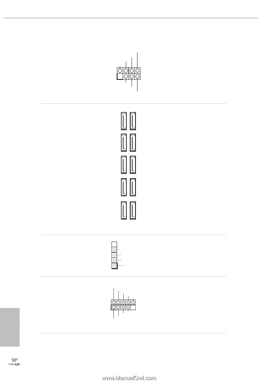
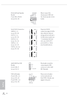
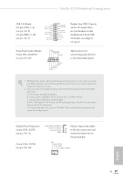
SATA3_A1 SATA3_7 SATA3_5 SATA3_3 SATA3_1 SATA3_A2 SATA3_8 SATA3_6 SATA3_4 SATA3_2 Power LED and Speaker Header (7-pin SPK_PLED1) (see p.1, No. 23) Serial ATA3 Connectors (SATA3_1_2: see p.1, No. 12) (SATA3_3_4: see p.1, No. 13) (SATA3_5_6: see p.1, No. 14) (SATA3_7_8: see p.1, No. 15) (SATA3_A1_A2: see p.1, No. 16) SPEAKER DUMMY DUMMY +5V 1 PLED+ PLED+ PLED- Please connect the chassis power LED and the chassis speaker to this header. These ten SATA3 connectors support SATA data cables for internal storage devices with up to 6.0 Gb/s data transfer rate. * To minimize the boot time, use AMD SATA ports (SATA3_1~8) for your bootable devices. AMD LED Fan USB Header (4-pin USB_5) (see p.1, No. 9) USB 2.0 Headers (9-pin USB_1_2) (see p.1, No. 21) (9-pin USB_3_4) (see p.1, No. 22) GND P+ PUSB_PWR 1 USB_PWR PP+ GND DUMMY 1 GND P+ PUSB_PWR This header is used for connecting the USB connector on the AMD SR3 Heatsink. There are two headers on this motherboard. Each USB 2.0 header can support two ports. 28 English
-
 1
1 -
2
-
3
-
4
-
5
-
6
-
7
-
8
-
9
-
10
-
11
-
12
-
13
-
14
-
15
-
16
-
17
-
18
-
19
-
20
-
21
-
22
-
23
-
24
-
25
-
26
-
 27
27 -
 28
28 -
 29
29 -
 30
30 -
 31
31 -
 32
32 -
 33
33 -
 34
34 -
 35
35 -
 36
36 -
 37
37 -
38
-
39
-
40
-
41
-
42
-
43
-
44
-
45
-
46
-
47
-
48
-
49
-
50
-
51
-
52
-
53
-
54
-
55
-
56
-
57
-
58
-
59
-
60
-
61
-
62
-
63
-
64
-
65
-
66
-
67
-
68
-
69
-
70
-
71
-
72
-
73
-
74
-
75
-
76
-
77
-
78
-
79
-
80
-
81
-
82
-
83
-
84
-
85
-
86
-
87
-
88
-
89
-
90
-
91
-
92
-
93
-
94
-
95
-
96
-
97
-
98
-
99
-
100
-
101
-
102
-
103
-
104
-
105
-
106
-
107
-
108
-
109
-
110
-
111
-
112
-
113
-
114
-
115
-
116
-
117
-
118
-
119
-
120
-
121
-
122
-
123
-
124
-
125
-
126
-
127
-
128
-
129
-
130
-
131
-
132
-
133
-
134
-
135
-
136
-
137
-
138
-
139
-
140
-
141
-
142
-
143
-
144
-
145
-
146
-
147
-
148
-
149
-
150
-
151
-
152
-
153
-
154
-
155
-
156
-
157
-
158
-
159
-
160
-
161
-
162
-
163
-
164
-
165
-
166
-
167
-
168
-
169
-
170
-
171
-
172
-
173
-
174
-
175
-
176
-
177
-
178
-
179
-
180
-
181
-
182
-
183
-
184
-
185
-
186
-
187
-
188
-
189
-
190
-
191
-
192
-
193
 |
 |