ASRock Fatal1ty X99X Killer User Manual - Page 12
English
 |
View all ASRock Fatal1ty X99X Killer manuals
Add to My Manuals
Save this manual to your list of manuals |
Page 12 highlights
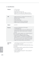
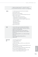
• 2 x RJ-45 LAN Ports with LED (ACT/LINK LED and SPEED LED) • 1 x Clear CMOS Switch • HD Audio Jacks: Rear Speaker / Central / Bass / Line in / Front Speaker / Microphone Storage • 10 x SATA3 6.0 Gb/s Connectors, support RAID (RAID 0, RAID 1, RAID 5, RAID 10 and Intel Rapid Storage 13), NCQ, AHCI, Hot Plug and ASRock HDD Saver Technology (SSATA3_3 connector is shared with the eSATA port) (SSATA3_2 connector is shared with Ultra M.2 Socket) * RAID is supported on SATA3_0 ~ SATA3_5 ports only. • 1 x eSATA Connector, supports NCQ, AHCI and Hot Plug • 1 x Ultra M.2 Socket, supports M.2 SATA3 6.0 Gb/s module and M.2 PCI Express module up to Gen3 x4 (32 Gb/s) Connector • 1 x COM Port Header • 1 x TPM Header • 1 x Power LED Header • 2 x CPU Fan Connectors (1 x 4-pin, 1 x 3-pin) • 3 x Chassis Fan Connectors (1 x 4-pin, 2 x 3-pin) (Smart Fan Speed Control) • 1 x Power Fan Connector (3-pin) • 1 x 24 pin ATX Power Connector • 1 x 8 pin 12V Power Connector (Hi-Density Power Connector) • 1 x HDD Saver Connector • 1 x PCIe Power Connector • 1 x Front Panel Audio Connector • 1 x Thunderbolt AIC Connector • 2 x USB 2.0 Headers (support 4 USB 2.0 ports) (Supports ESD Protection (ASRock Full Spike Protection)) • 1 x Vertical Type A USB 2.0 • 2 x USB 3.0 Headers (Support 4 USB 3.0 ports) (Supports ESD Protection (ASRock Full Spike Protection)) • 1 x Dr. Debug with LED • 1 x Power Switch with LED • 1 x Reset Switch with LED • 1 x BIOS Selection Switch English 4
-
 1
1 -
2
-
3
-
4
-
5
-
6
-
 7
7 -
 8
8 -
 9
9 -
 10
10 -
 11
11 -
 12
12 -
 13
13 -
 14
14 -
 15
15 -
 16
16 -
 17
17 -
18
-
19
-
20
-
21
-
22
-
23
-
24
-
25
-
26
-
27
-
28
-
29
-
30
-
31
-
32
-
33
-
34
-
35
-
36
-
37
-
38
-
39
-
40
-
41
-
42
-
43
-
44
-
45
-
46
-
47
-
48
-
49
-
50
-
51
-
52
-
53
-
54
-
55
-
56
-
57
-
58
-
59
-
60
-
61
-
62
-
63
-
64
-
65
-
66
-
67
-
68
-
69
-
70
-
71
-
72
-
73
-
74
-
75
-
76
-
77
-
78
-
79
-
80
-
81
-
82
-
83
-
84
-
85
-
86
-
87
-
88
-
89
-
90
-
91
-
92
-
93
-
94
-
95
-
96
-
97
-
98
-
99
-
100
-
101
-
102
-
103
-
104
-
105
-
106
-
107
-
108
-
109
-
110
-
111
-
112
-
113
-
114
-
115
 |
 |
