ASRock Fatal1ty Z97M Killer User Manual - Page 29
and the M.2_SSD NGFF, He SATA Express
 |
View all ASRock Fatal1ty Z97M Killer manuals
Add to My Manuals
Save this manual to your list of manuals |
Page 29 highlights
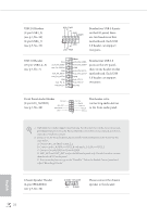
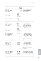
Fatal1ty Z97M Killer Series Power LED Header (3-pin PLED1) (see p.7, No. 17) Serial ATA3 Connectors (SATA3_0) (see p.7, No. 8) (SATA3_1) (see p.7, No. 10) (SATA3_2) (see p.7, No. 12) (SATA3_3) (see p.7, No. 9) (SATA3_4) (see p.7, No. 11) (SATA3_5) (see p.7, No. 13) SATA3_2 SATA3_5 SATA3_1 SATA3_0 1 PLEDPLED+ PLED+ SATA3_4 SATA3_3 Please connect the chassis power LED to this header to indicate the system's power status. hese six SATA3 connectors support SATA data cables for internal storage devices with up to 6.0 Gb/s data transfer rate. he SATA3_4, SATA3_5 are shared with the SATA Express connector. he SATA3_1 is shared with the eSATA1 port on the I/O panel.. Serial ATA Express Connector (SATAE_1) (see p.7, No. 14) SATAE_1 Please connect either SATA or PCIe storage devices to this connector. he SATA Express connector is shared with the SATA3_4, SATA3_5 and the M.2_SSD (NGFF) Socket 3. *he SATA Express interface is a combination of SATAE_1, SATA3_4, and SATA3_5. English 21
-
 1
1 -
2
-
3
-
4
-
5
-
6
-
7
-
8
-
9
-
10
-
11
-
12
-
13
-
14
-
15
-
16
-
17
-
18
-
19
-
20
-
21
-
22
-
23
-
 24
24 -
 25
25 -
 26
26 -
 27
27 -
 28
28 -
 29
29 -
 30
30 -
 31
31 -
 32
32 -
 33
33 -
 34
34 -
35
-
36
-
37
-
38
-
39
-
40
-
41
-
42
-
43
-
44
-
45
-
46
-
47
-
48
-
49
-
50
-
51
-
52
-
53
-
54
-
55
-
56
-
57
-
58
-
59
-
60
-
61
-
62
-
63
-
64
-
65
-
66
-
67
-
68
-
69
-
70
-
71
-
72
-
73
-
74
-
75
-
76
-
77
-
78
-
79
-
80
-
81
-
82
-
83
-
84
-
85
-
86
-
87
-
88
-
89
-
90
-
91
-
92
-
93
-
94
-
95
-
96
-
97
-
98
-
99
-
100
-
101
-
102
-
103
-
104
-
105
-
106
-
107
-
108
-
109
-
110
-
111
-
112
-
113
-
114
-
115
-
116
-
117
-
118
-
119
-
120
-
121
-
122
-
123
 |
 |
