ASRock G31M-GS User Manual - Page 10
Intel, Chipset - g31 m s
 |
View all ASRock G31M-GS manuals
Add to My Manuals
Save this manual to your list of manuals |
Page 10 highlights
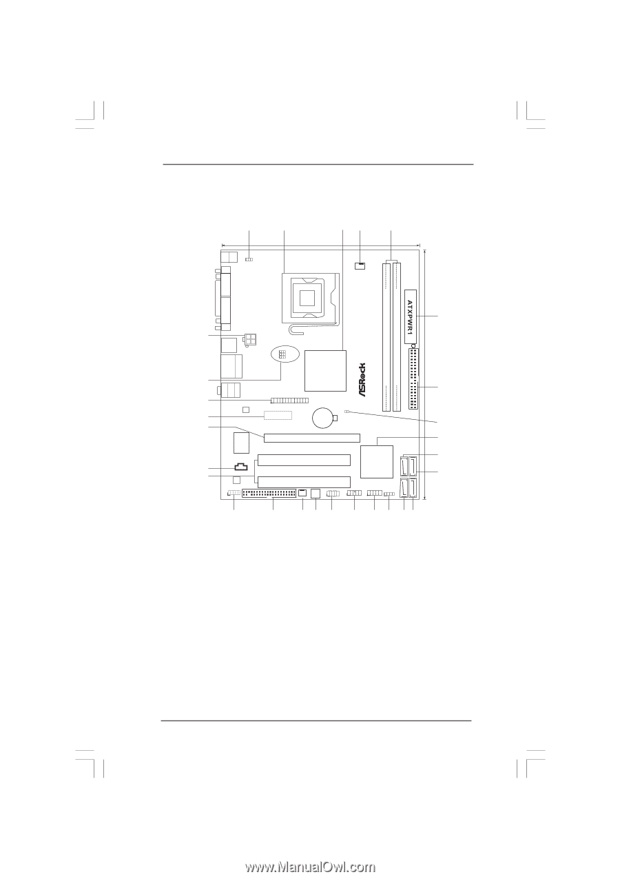
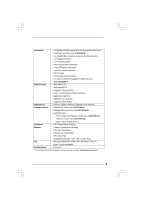
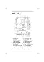
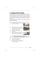
1.3 Motherboard Layout 1 2 34 5 19.1cm (7.5 in) 1 PS2_USB_PWR1 CPU_FAN1 PS2 Mouse PS2 Keyboard COM1 FSB1600 DDR2 800 Dual Channel DDRII_1 (64 bit, 240-piFnSmBod8ul0e)0 DDRII_2 (64 bit, 240-piFnSmBod8ul0e)0 24.4cm (9.6 in) VGA1 28 27 26 25 24 23 22 Top: Line In Center: Line Out Bottom: Mic In USB 2.0 T: USB2 B: USB3 ATX12V1 USB 2.0 T: USB0 B: USB1 Top: RJ-45 1 OC 800 1 FSB0 1 FSB1 Intel G31 Chipset LPT1 1 LAN PHY PCIE1 CMOS Battery CLRCMOS1 IDE1 Super IO CD1 RoHS AUDIO CODEC HD_AUDIO1 FLOPPY1 1 21 20 PCIE2 SATAII_3 PCI1 Intel ICH7 PCI2 CHA_FAN1 4Mb BIOS PANEL 1 PLED PWRBTN 1 HDLED RESET USB4_5 1 USB6_7 1 SPEAKER1 1 SATAII_1 19 18 17 16 15 14 13 12 SATAII_2 SATAII_4 6 7 8 9 10 11 1 PS2_USB_PWR1 Jumper 15 USB 2.0 Header (USB6_7, Blue) 2 775-Pin CPU Socket 16 USB 2.0 Header (USB4_5, Blue) 3 North Bridge Controller 17 System Panel Header (PANEL1, Orange) 4 CPU Fan Connector (CPU_FAN1) 18 BIOS SPI Chip 5 2 x 240-pin DDR2 DIMM Slots 19 Chassis Fan Connector (CHA_FAN1) (Dual Channel: DDRII_1, DDRII_2; Yellow) 20 Floppy Connector (FLOPPY1) 6 ATX Power Connector (ATXPWR1) 21 Front Panel Audio Header 7 IDE1 Connector (IDE1, Blue) (HD_AUDIO1, Lime) 8 Clear CMOS Jumper (CLRCMOS1) 22 PCI Slots (PCI1- 2) 9 South Bridge Controller 23 Internal Audio Connector: CD1 (Black) 10 Third SATAII Connector (SATAII_3; Orange) 24 PCI Express x16 Slot (PCIE2) 11 Fourth SATAII Connector (SATAII_4; Orange) 25 PCI Express x1 Slot (PCIE1) 12 Secondary SATAII Connector (SATAII_2; Red) 26 Print Port Header (LPT1, Purple) 13 Primary SATAII Connector (SATAII_1; Red) 27 OC 800 / FSB0 / FSB1 Jumper 14 Chassis Speaker Header (SPEAKER 1, Purple) 28 ATX 12V Connector (ATX12V1) 10
-
 1
1 -
2
-
3
-
4
-
 5
5 -
 6
6 -
 7
7 -
 8
8 -
 9
9 -
 10
10 -
 11
11 -
 12
12 -
 13
13 -
 14
14 -
 15
15 -
16
-
17
-
18
-
19
-
20
-
21
-
22
-
23
-
24
-
25
-
26
-
27
-
28
-
29
-
30
-
31
-
32
-
33
-
34
-
35
-
36
-
37
-
38
-
39
-
40
-
41
-
42
-
43
-
44
-
45
 |
 |