ASRock G31M-VS User Manual - Page 21
ASRock G31M-VS Manual
 |
View all ASRock G31M-VS manuals
Add to My Manuals
Save this manual to your list of manuals |
Page 21 highlights
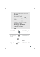
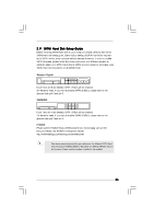
E. Enter BIOS Setup Utility. Enter Advanced Settings, and then select Chipset Configuration. Set the Front Panel Control option from [Auto] to [Enabled]. F. Enter Windows system. Click the icon on the lower right hand taskbar to enter Realtek HD Audio Manager. For Windows® 2000 / XP / XP 64-bit OS: Click "Audio I/O", select "Connector Settings" , choose "Disable front panel jack detection", and save the change by clicking "OK". For Windows® VistaTM / VistaTM 64-bit OS: Click the right-top "Folder" icon , choose "Disable front panel jack detection", and save the change by clicking "OK". G. To activate the front mic. For Windows® 2000 / XP / XP 64-bit OS: Please select "Front Mic" as default record device. If you want to hear your voice through front mic, please deselect "Mute" icon in "Front Mic" of "Playback" portion. For Windows® VistaTM / VistaTM 64-bit OS: Go to the "Front Mic" Tab in the Realtek Control panel. Click "Set Default Device" to make the Front Mic as the default record device. System Panel Header (9-pin PANEL1) (see p.10 No. 9) 1 PLE D + PLE D PW RB TN# GND This header accommodates several system front panel functions. DU MMY R E S ET# GND H D LE D H D LE D + Chassis Speaker Header (4-pin SPEAKER 1) (see p.10 No. 10) 1 S PEAKE R DU MMY DU MMY +5V Please connect the chassis speaker to this header. Chassis Fan Connector (3-pin CHA_FAN1) (see p.10 No. 14) GND +1 2 V CHA_FAN_S P EED Please connect a chassis fan cable to this connector and match the black wire to the ground pin. Please connect a CPU fan cable to this connector and match the black wire to the ground pin. CPU Fan Connector (4-pin CPU_FAN1) (see p.10 No. 3) GND +12V C P U _FAN_ S PEE D FAN_ S PEE D _ C ONT R OL 1 2 3 4 21
-
 1
1 -
2
-
3
-
4
-
5
-
6
-
7
-
8
-
9
-
10
-
11
-
12
-
13
-
14
-
15
-
 16
16 -
 17
17 -
 18
18 -
 19
19 -
 20
20 -
 21
21 -
 22
22 -
 23
23 -
 24
24 -
 25
25 -
 26
26 -
27
-
28
-
29
-
30
-
31
-
32
-
33
-
34
-
35
-
36
-
37
-
38
-
39
-
40
-
41
-
42
-
43
 |
 |
