ASRock G41C-GS User Manual - Page 24
Chassis and Power Fan Connectors - cpu
 |
View all ASRock G41C-GS manuals
Add to My Manuals
Save this manual to your list of manuals |
Page 24 highlights
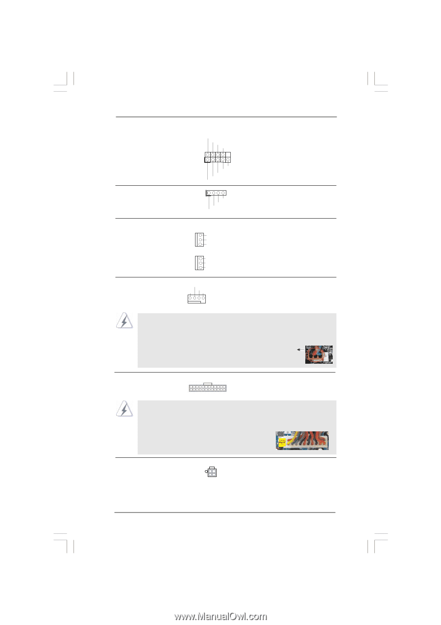
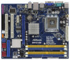
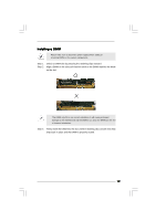
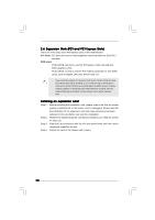
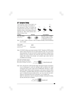
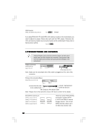
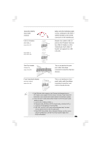
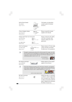
System Panel Header (9-pin PANEL1) (see p.11 No. 19) Chassis Speaker Header (4-pin SPEAKER 1) (see p.11 No. 14) PLED+ PLEDPWRBTN# GND 1 DUMMY RESET# GND HDLEDHDLED+ 1 SPEAKER DUMMY DUMMY +5V This header accommodates several system front panel functions. Please connect the chassis speaker to this header. Chassis and Power Fan Connectors (3-pin CHA_FAN1) (see p.11 No. 10) GND +12V CHA_FAN_SPEED (3-pin PWR_FAN1) (see p.11 No. 9) GND +12V PWR_FAN_SPEED Please connect the fan cables to the fan connectors and match the black wire to the ground pin. CPU Fan Connector (4-pin CPU_FAN1) (see p.11 No. 3) +12V CPU_FAN_SPEED GND FAN_SPEED_CONTROL 1 2 3 4 Please connect a CPU fan cable to this connector and match the black wire to the ground pin. Though this motherboard provides 4-Pin CPU fan (Quiet Fan) support, the 3-Pin CPU fan still can work successfully even without the fan speed control function. If you plan to connect the 3-Pin CPU fan to the CPU fan connector on this motherboard, please connect it to Pin 1-3. Pin 1-3 Connected 3-Pin Fan Installation ATX Power Connector 24 (24-pin ATXPWR1) (see p.11 No. 4) 12 Please connect an ATX power 13 supply to this connector. 1 Though this motherboard provides 24-pin ATX power connector, it can still work if you adopt a traditional 20-pin ATX power supply. To use the 20-pin ATX power supply, please plug your power supply along with Pin 1 and Pin 13. 24 13 ATX 12V Connector (4-pin ATX12V2) (see p.11 No. 2) 24 20-Pin ATX Power Supply Installation 12 1 Please note that it is necessary to connect a power supply with ATX 12V plug to this connector so that it can provides sufficient power. Failing to do so will cause the failure to power up.
-
 1
1 -
2
-
3
-
4
-
5
-
6
-
7
-
8
-
9
-
10
-
11
-
12
-
13
-
14
-
15
-
16
-
17
-
18
-
 19
19 -
 20
20 -
 21
21 -
 22
22 -
 23
23 -
 24
24 -
 25
25 -
 26
26 -
 27
27 -
 28
28 -
 29
29 -
30
-
31
-
32
-
33
-
34
-
35
-
36
-
37
-
38
-
39
-
40
-
41
-
42
-
43
-
44
-
45
-
46
-
47
-
48
-
49
-
50
-
51
-
52
-
53
 |
 |