ASRock G41M-VS3 R2.0 Quick Installation Guide - Page 18
English, 6 Onboard Headers and Connectors
 |
View all ASRock G41M-VS3 R2.0 manuals
Add to My Manuals
Save this manual to your list of manuals |
Page 18 highlights
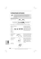
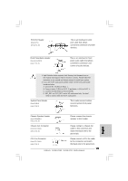
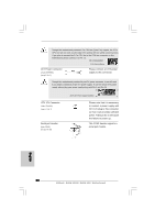
2.6 Onboard Headers and Connectors Onboard headers and connectors are NOT jumpers. Do NOT place jumper caps over these headers and connectors. Placing jumper caps over the headers and connectors will cause permanent damage of the motherboard! Primary IDE connector (Blue) (39-pin IDE1, see p.2 No. 9) connect the blue end connect the black end to the motherboard to the IDE devices 80-conductor ATA 66/100 cable Note: Please refer to the instruction of your IDE device vendor for the details. Serial ATAII Connectors (SATAII_1: see p.2, No. 10) (SATAII_2: see p.2, No. 11) SATAII_4 SATAII_3 (SATAII_3: see p.2, No. 12) (SATAII_4: see p.2, No. 13) SATAII_2 SATAII_1 These Serial ATAII (SATAII) connectors support SATAII or SATA hard disk for internal storage devices. The current SATAII interface allows up to 3.0 Gb/s data transfer rate. Serial ATA (SATA) Data Cable (Optional) Either end of the SATA data cable can be connected to the SATA / SATAII hard disk or the SATAII connector on the motherboard. USB 2.0 Headers (9-pin USB6_7) (see p.2 No. 17) (9-pin USB4_5) (see p.2 No. 15) Besides four default USB 2.0 ports on the I/O panel, there are two USB 2.0 headers on this motherboard. Each USB 2.0 header can support two USB 2.0 ports. English 18 ASRock G41M-VGS3 / G41M-VS3 Motherboard
-
 1
1 -
2
-
3
-
4
-
5
-
6
-
7
-
8
-
9
-
10
-
11
-
12
-
 13
13 -
 14
14 -
 15
15 -
 16
16 -
 17
17 -
 18
18 -
 19
19 -
 20
20 -
 21
21 -
 22
22 -
 23
23 -
24
-
25
-
26
-
27
-
28
-
29
-
30
-
31
-
32
-
33
-
34
-
35
-
36
-
37
-
38
-
39
-
40
-
41
-
42
-
43
-
44
-
45
-
46
-
47
-
48
-
49
-
50
-
51
-
52
-
53
-
54
-
55
-
56
-
57
-
58
-
59
-
60
-
61
-
62
-
63
-
64
-
65
-
66
-
67
-
68
-
69
-
70
-
71
-
72
-
73
-
74
-
75
-
76
-
77
-
78
-
79
-
80
-
81
-
82
-
83
-
84
-
85
-
86
-
87
-
88
-
89
-
90
-
91
-
92
-
93
-
94
-
95
-
96
-
97
-
98
-
99
-
100
-
101
-
102
-
103
-
104
-
105
-
106
-
107
-
108
-
109
-
110
-
111
-
112
-
113
-
114
-
115
-
116
-
117
-
118
-
119
-
120
-
121
-
122
-
123
-
124
-
125
-
126
-
127
-
128
-
129
-
130
-
131
-
132
-
133
-
134
-
135
-
136
-
137
-
138
-
139
-
140
-
141
-
142
-
143
-
144
-
145
-
146
-
147
-
148
-
149
-
150
-
151
-
152
-
153
-
154
-
155
-
156
-
157
 |
 |
