ASRock H110M-DVS/D3 User Manual - Page 26
Platform Module TPM system, ATX 12V Power
 |
View all ASRock H110M-DVS/D3 manuals
Add to My Manuals
Save this manual to your list of manuals |
Page 26 highlights
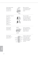
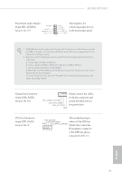
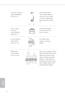
ATX Power Connector (24-pin ATXPWR1) (see p.6, No. 4) ATX 12V Power Connector (4-pin ATX12V1) (see p.6, No. 1) Serial Port Header (9-pin COM1) (see p.6, No. 15) 1 13 12 24 This motherboard provides a 24-pin ATX power connector. To use a 20-pin ATX power supply, please plug it along Pin 1 and Pin 13. This motherboard provides a 4-pin ATX 12V power connector. RRXD1 DDTR#1 DDSR#1 CCTS#1 1 RRI#1 RRTS#1 GND TTXD1 DDCD#1 This COM1 header supports a serial port module. GND SMB_CLK_MAIN SMB_DATA_MAIN LAD2 LAD1 GND S_PWRDWN# SERIRQ# GND TPM Header (17-pin TPMS1) (see p.6, No. 14) 1 PCICLK FRAME PCIRST# LAD3 +3V LAD0 +3VSB GND This connector supports Trusted Platform Module (TPM) system, which can securely store keys, digital certificates, passwords, and data. A TPM system also helps enhance network security, protects digital identities, and ensures platform integrity. English 22
-
 1
1 -
2
-
3
-
4
-
5
-
6
-
7
-
8
-
9
-
10
-
11
-
12
-
13
-
14
-
15
-
16
-
17
-
18
-
19
-
20
-
 21
21 -
 22
22 -
 23
23 -
 24
24 -
 25
25 -
 26
26 -
 27
27 -
 28
28 -
 29
29 -
 30
30 -
 31
31 -
32
-
33
-
34
-
35
-
36
-
37
-
38
-
39
-
40
-
41
-
42
-
43
-
44
-
45
-
46
-
47
-
48
-
49
-
50
-
51
-
52
-
53
-
54
-
55
-
56
-
57
-
58
-
59
-
60
-
61
-
62
-
63
-
64
-
65
-
66
-
67
-
68
-
69
-
70
 |
 |
