ASRock H110M-I User Manual
ASRock H110M-I Manual
 |
View all ASRock H110M-I manuals
Add to My Manuals
Save this manual to your list of manuals |
ASRock H110M-I manual content summary:
- ASRock H110M-I | User Manual - Page 1
H110M-I - ASRock H110M-I | User Manual - Page 2
change without notice, and should not be constructed as a commitment by ASRock. ASRock assumes no responsibility for any errors or omissions that may appear in CALIFORNIA, USA ONLY The Lithium battery adopted on this motherboard contains Perchlorate, a toxic substance controlled in Perchlorate Best - ASRock H110M-I | User Manual - Page 3
1 Introduction 1 1.1 Package Contents 1 1.2 Specifications 2 1.3 Motherboard Layout 5 1.4 I/O Panel 7 Chapter 2 Installation 9 2.1 17 Chapter 3 Software and Utilities Operation 21 3.1 Installing Drivers 21 3.2 ASRock Live Update & APP Shop 22 3.2.1 UI Overview 22 3.2.2 Apps 23 - ASRock H110M-I | User Manual - Page 4
4.3 Advanced Mode 33 4.3.1 UEFI Menu Bar 33 4.3.2 Navigation Keys 34 4.4 Main Screen 35 4.5 OC Tweaker Screen 36 4.6 Advanced Screen 44 4.6.1 CPU Configuration 45 4.6.2 Chipset Configuration 47 4.6.3 Storage Configuration 49 4.6.4 ACPI Configuration 50 4.6.5 USB Configuration 52 - ASRock H110M-I | User Manual - Page 5
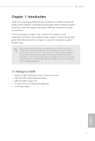
may find the latest VGA cards and CPU support list on ASRock's website as well. ASRock website http://www.asrock.com. 1.1 Package Contents • ASRock H110M-I Motherboard (Micro ATX Form Factor) • ASRock H110M-I Quick Installation Guide • ASRock H110M-I Support CD • 2 x Serial ATA (SATA) Data Cables - ASRock H110M-I | User Manual - Page 6
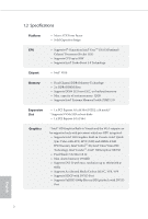
boot disks • 1 x PCI Express 2.0 x1 Slot Graphics * Intel® HD Graphics Built-in Visuals and the VGA outputs can be supported only with processors which are GPU integrated. • Supports Intel® HD Graphics Built-in Visuals : Intel® Quick Sync Video with AVC, MVC (S3D) and MPEG-2 Full HW Encode1, Intel - ASRock H110M-I | User Manual - Page 7
H110M-I Audio • 7.1 CH HD Audio (Realtek ALC887 Audio Codec) * To configure 7.1 CH HD Audio, it is required to use an HD front panel audio module and enable the multi-channel audio feature through the audio driver. • Supports Surge Protection (ASRock Full Spike Protection) • ELNA Audio Caps LAN - ASRock H110M-I | User Manual - Page 8
into the ISO file is required. Please refer to page 28 for more detailed instructions. * For the updated Windows® 10 driver, please visit ASRock's website for details: http://www.asrock.com Certifications • FCC, CE, WHQL English * For detailed product information, please visit our website - ASRock H110M-I | User Manual - Page 9
1.3 Motherboard Layout 1 2 PS 2 Mouse PS2 Keyboard ATX12V1 CPU_FAN1 H110M-I 3 4 CHA_FAN1 DVI1 DDR4_A1 (64 bit, 288-pin module) DDR4_B1 (64 bit,288-pin module) SPK_CI1 USB_4_5 PLED PWRBTN HDLED RESET PCIE1 1 1 8 BIOS ROM H110M-I 1 TPMS1 9 PCIE2 CLRMOS1 15 14 13 12 11 10 English 5 - ASRock H110M-I | User Manual - Page 10
No. Description 1 ATX 12V Power Connector (ATX12V1) 2 CPU Fan Connector (CPU_FAN1) 3 2 x 288-pin DDR3/DDR3L DIMM Slots (DDR4_A1, DDR4_B1) 4 Chassis Fan Connector (CHA_FAN1) 5 ATX Power Connector (ATXPWR1) 6 USB 3.0 Header (USB3_3_4) 7 SATA3 Connector (SATA3_0) 8 TPM Header (TPMS1) 9 USB 2.0 Header ( - ASRock H110M-I | User Manual - Page 11
1.4 I/O Panel 1 H110M-I 2 3 4 10 9 No. Description 1 PS/2 Mouse Port (Green)*** 2 LAN RJ-45 Port* 3 Line In (Light Blue)** 4 Front Speaker (Lime)** 5 Microphone (Pink)** 8 7 6 5 No. Description 6 USB 2.0 Ports (USB23)*** 7 - ASRock H110M-I | User Manual - Page 12
HD Audio Manager. Function of the Audio Ports in 7.1-channel Configuration: Port Light Blue (Rear panel) Lime (Rear panel) Pink (Rear panel) Lime (Front panel) ***Supports ACPI wake-up function Function Rear Speaker Out Front Speaker Out Central /Subwoofer Speaker Out Side Speaker Out 8 English - ASRock H110M-I | User Manual - Page 13
H110M-I Chapter 2 Installation This is a Micro ATX form factor motherboard. Before you install the motherboard, study the configuration of your chassis to ensure that the motherboard fits into it. Pre-installation Precautions Take note of the following precautions before you install motherboard - ASRock H110M-I | User Manual - Page 14
2.1 Installing the CPU 1. Before you insert the 1151-Pin CPU into the socket, please check if the PnP cap is on the socket, if the CPU surface is unclean, or if there are any bent pins in the socket. Do not force to insert the CPU into the socket if above situation is found. Otherwise, the CPU will - ASRock H110M-I | User Manual - Page 15
H110M-I 3 4 5 11 English - ASRock H110M-I | User Manual - Page 16
Please save and replace the cover if the processor is removed. The cover must be placed if you wish to return the motherboard for after service. 12 English - ASRock H110M-I | User Manual - Page 17
2.2 Installing the CPU Fan and Heatsink H110M-I 1 2 CPU_FAN English 13 - ASRock H110M-I | User Manual - Page 18
2.3 Installing Memory Modules (DIMM) This motherboard provides two 288-pin DDR4 (Double Data Rate 4) DIMM slots, and supports Dual Channel Memory Technology. 1. For dual channel configuration, you always need to install identical (the same brand, speed, size and chip-type) DDR4 DIMM pairs. 2. - ASRock H110M-I | User Manual - Page 19
H110M-I 1 2 3 15 English - ASRock H110M-I | User Manual - Page 20
2.4 Expansion Slots (PCI Express Slots) There are 2 PCI Express slots on the motherboard. Before installing an expansion card, please make sure that the power supply is switched off or the power cord is unplugged. Please read the documentation - ASRock H110M-I | User Manual - Page 21
H110M-I 2.5 Onboard Headers and Connectors Onboard headers and connectors are NOT jumpers. Do NOT place jumper caps over these headers and connectors. Placing jumper caps over the headers and connectors will cause permanent damage to the motherboard. System Panel Header (9-pin PANEL1) (see p.5, No. - ASRock H110M-I | User Manual - Page 22
USB_PWR PP+ GND DUMMY Besides four USB 2.0 ports on the I/O panel, there is one header on this motherboard. Each USB 2.0 header can support two ports. USB 3.0 Header (19-pin USB3_3_4) (see p.5, No. 6) Vbus IntA_PA_SSRXIntA_PA_SSRX+ GND IntA_PA_SSTXIntA_PA_SSTX+ GND IntA_PA_DIntA_PA_D+ Besides - ASRock H110M-I | User Manual - Page 23
supports Jack Sensing, but the panel wire on the chassis must support HDA to function correctly. Please follow the instructions in our manual and chassis manual Connector (4-pin CPU_FAN1) (see p.5, No. 2) This motherboard pro- FAN_VOLTAGE CPU_FAN_SPEED vides a 4-Pin CPU fan GND - ASRock H110M-I | User Manual - Page 24
(see p.5, No. 1) TPM Header (17-pin TPMS1) (see p.5, No. 8) 5 1 8 4 This motherboard provides a 8-pin ATX 12V power connector. 1 PCICLK FRAME PCIRST# LAD3 +3V LAD0 +3VSB GND This connector supports Trusted GND SMB_CLK_MAIN Platform Module (TPM) system, SMB_DATA_MAIN which can securely store - ASRock H110M-I | User Manual - Page 25
H110M-I Chapter 3 Software and Utilities Operation 3.1 Installing Drivers The Support CD that comes with the motherboard contains necessary drivers and useful utilities that enhance the motherboard's features. Running The Support CD To begin using the support CD, insert the CD into your CD-ROM drive - ASRock H110M-I | User Manual - Page 26
purchasing and downloading software applications for your ASRock computer. You can quickly and easily install various apps and support utilities, such as USB Key, XFast LAN, XFast RAM and more. With ASRock APP Shop, you can optimize your system and keep your motherboard up to date simply with a few - ASRock H110M-I | User Manual - Page 27
H110M-I 3.2.2 Apps When the "Apps" tab is selected, you will see all the available apps on screen for you to download. Installing an App Step 1 Find - ASRock H110M-I | User Manual - Page 28
Step 3 If you want to install the app, click on the red icon to start downloading. Step 4 When installation completes, you can find the green "Installed" icon appears on the upper right corner. English To uninstall it, simply click on the trash can icon . *The trash icon may not appear for - ASRock H110M-I | User Manual - Page 29
H110M-I Upgrading an App You can only upgrade the apps you have already installed. When there is an available new version for your app, you will - ASRock H110M-I | User Manual - Page 30
3.2.3 BIOS & Drivers Installing BIOS or Drivers When the "BIOS & Drivers" tab is selected, you will see a list of recommended or critical updates for the BIOS or drivers. Please update them all soon. Step 1 Please check the item information before update. Click on Step 2 to see more details. - ASRock H110M-I | User Manual - Page 31
H110M-I 3.2.4 Setting In the "Setting" page, you can change the language, select the server location, and determine if you want to automatically run the ASRock Live Update & APP Shop on Windows startup. 27 English - ASRock H110M-I | User Manual - Page 32
7 operating system because the USB ports on their motherboard won't work. In order for the USB ports ASRock Support CD or website) Scenarios You have an ODD and PS/2 ports: If there is an optical disc drive, PS/2 ports and PS/2 Keyboard or mouse on your computer, you can skip the instructions - ASRock H110M-I | User Manual - Page 33
H110M-I Instructions Step 1 Insert the Windows® 7 installation disk or USB drive to your system. Step 2 Extract the tool (Win7 Driver Folder" by clicking the red circle as shown as the picture below. If you are using ASRock's Support CD for the USB 3.0 driver, please select your CD-ROM. 29 English - ASRock H110M-I | User Manual - Page 34
Step 5 Select where to save the ISO file by pressing the red circle as shown as the picture below. Step 6 If you want to burn the patched image to a CD, please check "Burn Image" and select "Target Device to Burn". If not, the patched ISO image will be exported to the destination selected in Step5. - ASRock H110M-I | User Manual - Page 35
H110M-I Chapter 4 UEFI SETUP UTILITY 4.1 Introduction This section explains how to use the UEFI SETUP UTILITY to configure your system. You may run the UEFI SETUP - ASRock H110M-I | User Manual - Page 36
4.2 EZ Mode The EZ Mode screen appears when you enter the BIOS setup program by default. EZ mode is a dashboard which contains multiple readings of the system's current status. You can check the most crucial information of your system, such as CPU speed, DRAM frequency, SATA information, fan speed, - ASRock H110M-I | User Manual - Page 37
H110M-I 4.3 Advanced Mode The Advanced Mode provides more options to configure the BIOS settings. Refer to the following sections for the detailed configurations. To access the - ASRock H110M-I | User Manual - Page 38
4.3.2 Navigation Keys Use < > key or < > key to choose among the selections on the menu bar, and use < > key or < > key to move the cursor up or down to select items, then press to get into the sub screen. You can also use the mouse to click your required item. Please check the following - ASRock H110M-I | User Manual - Page 39
H110M-I 4.4 Main Screen When you enter the UEFI SETUP UTILITY, the Main screen will appear and display the system overview. Favorite Display your collection of BIOS items. Press F5 to add/remove your favorite items. 35 English - ASRock H110M-I | User Manual - Page 40
4.5 OC Tweaker Screen In the OC Tweaker screen, you can set up overclocking features. Because the UEFI software is constantly being updated, the following UEFI setup screens and descriptions are for reference purpose only, and they may not exactly match what you see on your screen. CPU Configuration - ASRock H110M-I | User Manual - Page 41
H110M-I Long Duration Maintained Configure the period of time until the CPU ratio is Reference Clock Select Auto for optimized settings. DRAM Frequency If [Auto] is selected, the motherboard will detect the memory module(s) inserted and assign the appropriate frequency automatically. Primary Timing - ASRock H110M-I | User Manual - Page 42
Secondary Timing Write Recovery Time (tWR) The amount of delay that must elapse after the completion of a valid write operation, before an active bank can be precharged. Refresh Cycle Time (tRFC) The number of clocks from a Refresh command until the first Activate command to the same rank. RAS to - ASRock H110M-I | User Manual - Page 43
. tWRRD_dd Configure between module write to read delay. tWRWR_sg Configure between module write to write delay. tWRWR_dg Configure between module write to write delay. tWRWR_dr H110M-I 39 English - ASRock H110M-I | User Manual - Page 44
Configure between module write to write delay. tWRWR_dd Configure between module write to write delay. RTL Init Value Configure round trip latency init value for round trip latency training. IO-L Init Value Configure IO latency init value for IO latency traning. RTL (CH A) Configure round trip - ASRock H110M-I | User Manual - Page 45
. tRDPDEN Configure tRDPDEN. twRPDEN Configure twRPDEN. OREF_RI Configure OREF_RI. tREFIx9 Configure tREFIx9. txSDLL Configure txSDLL. txs_offset Configure txs_offset. tZQOPER Configure tZQOPER. tMOD Configure tMOD. ZQCS_period H110M-I 41 English - ASRock H110M-I | User Manual - Page 46
on die termination resistors' PARK for channel B. ODT NOM (CH A) Use this to change ODT (CH A) Auto/Manual settings. The default is [Auto]. ODT NOM (CH B) Use this to change ODT (CH B) Auto/Manual settings. The default is [Auto]. MRC Fast Boot Enable Memory Fast Boot to skip DRAM memory training for - ASRock H110M-I | User Manual - Page 47
current UEFI settings as an user default profile to disk. Load User UEFI Setup Profile from Disk Load previously saved user defaults from the disk. H110M-I English 43 - ASRock H110M-I | User Manual - Page 48
4.6 Advanced Screen In this section, you may set the configurations for the following items: CPU Configuration, Chipset Configuration, Storage Configuration, ACPI Configuration, USB Configuration and Trusted Computing. Setting wrong values in this section may cause the system to malfunction. UEFI - ASRock H110M-I | User Manual - Page 49
H110M-I Intel Hyper Threading Technology Intel Hyper Threading Technology allows multiple threads to run on each core, so that the overall performance on threaded software is improved. Active Processor Cores Select the number of cores to enable in each processor package. CPU C States Support - ASRock H110M-I | User Manual - Page 50
Enable CPU, PCIe, Memory, Graphics C State Support for power saving. CPU Thermal Throttling Enable CPU internal thermal control mechanisms to keep the CPU from overheating. No-Execute Memory Protection Processors with No- - ASRock H110M-I | User Manual - Page 51
4.6.2 Chipset Configuration H110M-I Primary Graphics Adapter Select a primary VGA. Top of Lower for PCIE2. PCIE ASPM Support This option enables/disables the ASPM support for all CPU downstream devices. PCH PCIE ASPM Support This option enables/disables the ASPM support for all PCH PCIE devices - ASRock H110M-I | User Manual - Page 52
This option enables/disables the control of ASPM on CPU side of the DMI Link. PCH DMI ASPM Support This option enables/disables the ASPM support for all PCH DMI devices. Share Memory Configure the size of memory that is allocated to the integrated graphics processor when the system boots up. - ASRock H110M-I | User Manual - Page 53
4.6.3 Storage Configuration H110M-I SATA Controller(s) Enable/disable the SATA controllers. SATA Aggressive Link Power Management SATA Aggressive Link Power Management allows SATA devices to enter a low power state during periods of inactivity to save power. It is only supported by AHCI mode. Hard - ASRock H110M-I | User Manual - Page 54
4.6.4 ACPI Configuration Suspend to RAM Select disable for ACPI suspend type S1. It is recommended to select auto for ACPI S3 power saving. ACPI HEPT Table Enable the High Precision Event Timer for better performance. PS/2 Keyboard Power On Allow the system to be waked up by a PS/2 Keyboard. PCIE - ASRock H110M-I | User Manual - Page 55
USB Mouse Power On Allow the system to be waked up by an USB mouse. H110M-I English 51 - ASRock H110M-I | User Manual - Page 56
for USB 2.0 devices. If you encounter USB compatibility issues it is recommended to disable legacy USB support. Select UEFI Setup Only to support USB devices under the UEFI setup and Windows/Linux operating systems only. PS/2 Stimulator Enable PS/2 Stimulator. This should be enabled for the complete - ASRock H110M-I | User Manual - Page 57
4.6.6 Trusted Computing H110M-I Security Device Support Enable or disable BIOS support for security device. English 53 - ASRock H110M-I | User Manual - Page 58
Contact ASRock Tech Service if you are having trouble with your PC. Please setup network configuration before using UEFI Tech Service. Easy Driver Installer For users that don't have an optical disk drive to install the drivers from our support CD, Easy Driver Installer is a handy tool in the - ASRock H110M-I | User Manual - Page 59
H110M-I Boot Manager Enable/disable the Boot Manager. Boot Manager Timeout Enable/disable device and run Instant Flash to update your UEFI. Internet Flash - DHCP (Auto IP), Auto ASRock Internet Flash downloads and updates the latest UEFI firmware version from our servers for you. Please setup - ASRock H110M-I | User Manual - Page 60
Internet Setting Enable or disable sound effects in the setup utility. UEFI Download Server Select a server to download the UEFI firmware. 56 English - ASRock H110M-I | User Manual - Page 61
H110M-I 4.8 Hardware Health Event Monitoring Screen This section allows you to monitor the status of the hardware on your system, including the parameters of the CPU temperature, motherboard temperature, fan speed and voltage. Fan-Tastic Tuning Select a fan mode for CPU Fans, or choose Customize to - ASRock H110M-I | User Manual - Page 62
Case Open Feature Enable or disable Case Open Feature to detect whether the chassis cover has been removed. 58 English - ASRock H110M-I | User Manual - Page 63
H110M-I 4.9 Security Screen In this section you may set or change the supervisor/ Leave it blank and press enter to remove the password. Secure Boot Use this item to enable or disable support for Windows 8.1 Secure Boot. Intel(R) Platform Trust Technology Enable/disable Intel PTT in ME. Disable this - ASRock H110M-I | User Manual - Page 64
minimizes your computer's boot time. In fast mode you may not boot from an USB storage device. Ultra Fast mode is only supported by Windows 8.1 and the VBIOS must support UEFI GOP if you are using an external graphics card. Please notice that Ultra Fast mode will boot so fast that the - ASRock H110M-I | User Manual - Page 65
H110M-I Full Screen Logo Enable to display the boot logo or disable to show normal POST messages. AddOn ROM Display Enable AddOn ROM Display to see - ASRock H110M-I | User Manual - Page 66
to not execute both legacy and UEFI option ROM. Launch Storage OpROM Policy Select UEFI only to run those that support UEFI option ROM only. Select Legacy only to run those that support legacy option ROM only. Select Do not launch to not execute both legacy and UEFI option ROM. Launch Video - ASRock H110M-I | User Manual - Page 67
4.11 Exit Screen H110M-I Save Changes and Exit When you select this option the following message, "Save configuration changes and exit setup?" will pop out. Select [OK] to save - ASRock H110M-I | User Manual - Page 68
or want to know more about ASRock, you're welcome to visit ASRock's website at http://www.asrock.com; or you may contact your dealer for further information. For technical questions, please submit a support request form at http://www.asrock.com/support/tsd.asp ASRock Incorporation 2F., No.37, Sec
-
 1
1 -
 2
2 -
 3
3 -
 4
4 -
 5
5 -
 6
6 -
 7
7 -
8
-
9
-
10
-
11
-
12
-
13
-
14
-
15
-
16
-
17
-
18
-
19
-
20
-
21
-
22
-
23
-
24
-
25
-
26
-
27
-
28
-
29
-
30
-
31
-
32
-
33
-
34
-
35
-
36
-
37
-
38
-
39
-
40
-
41
-
42
-
43
-
44
-
45
-
46
-
47
-
48
-
49
-
50
-
51
-
52
-
53
-
54
-
55
-
56
-
57
-
58
-
59
-
60
-
61
-
62
-
63
-
64
-
65
-
66
-
67
-
68
 |
 |
H110M-I