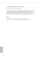
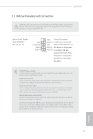
ASRock H110M-I User Manual - Page 24
Platform Module TPM system, Clear CMOS Pad.
 |
View all ASRock H110M-I manuals
Add to My Manuals
Save this manual to your list of manuals |
Page 24 highlights
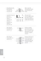
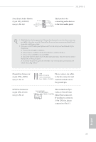
ATX Power Connector (24-pin ATXPWR1) (see p.5, No. 5) 1 13 12 24 This motherboard provides a 24-pin ATX power connector. To use a 20-pin ATX power supply, please plug it along Pin 1 and Pin 13. ATX 12V Power Connector (8-pin ATX12V1) (see p.5, No. 1) TPM Header (17-pin TPMS1) (see p.5, No. 8) 5 1 8 4 This motherboard provides a 8-pin ATX 12V power connector. 1 PCICLK FRAME PCIRST# LAD3 +3V LAD0 +3VSB GND This connector supports Trusted GND SMB_CLK_MAIN Platform Module (TPM) system, SMB_DATA_MAIN which can securely store keys, LAD2 LAD1 digital certificates, passwords, GND S_PWRDWN# and data. A TPM system also SERIRQ# GND helps enhance network security, protects digital identities, and ensures platform integrity. Clear CMOS Pad (CLRMOS1) (see p.5, No. 10) CLRMOS1 allows you to clear the data in CMOS. To clear CMOS, take out the CMOS battery and short the Clear CMOS Pad. English 20
-
 1
1 -
2
-
3
-
4
-
5
-
6
-
7
-
8
-
9
-
10
-
11
-
12
-
13
-
14
-
15
-
16
-
17
-
18
-
 19
19 -
 20
20 -
 21
21 -
 22
22 -
 23
23 -
 24
24 -
 25
25 -
 26
26 -
 27
27 -
 28
28 -
 29
29 -
30
-
31
-
32
-
33
-
34
-
35
-
36
-
37
-
38
-
39
-
40
-
41
-
42
-
43
-
44
-
45
-
46
-
47
-
48
-
49
-
50
-
51
-
52
-
53
-
54
-
55
-
56
-
57
-
58
-
59
-
60
-
61
-
62
-
63
-
64
-
65
-
66
-
67
-
68
 |
 |
