ASRock H370M-ITX/ac User Manual - Page 30
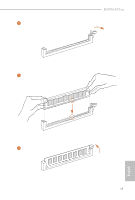
Chassis/Water Pump Fan, pin CHA_FAN1/WP
 |
View all ASRock H370M-ITX/ac manuals
Add to My Manuals
Save this manual to your list of manuals |
Page 30 highlights
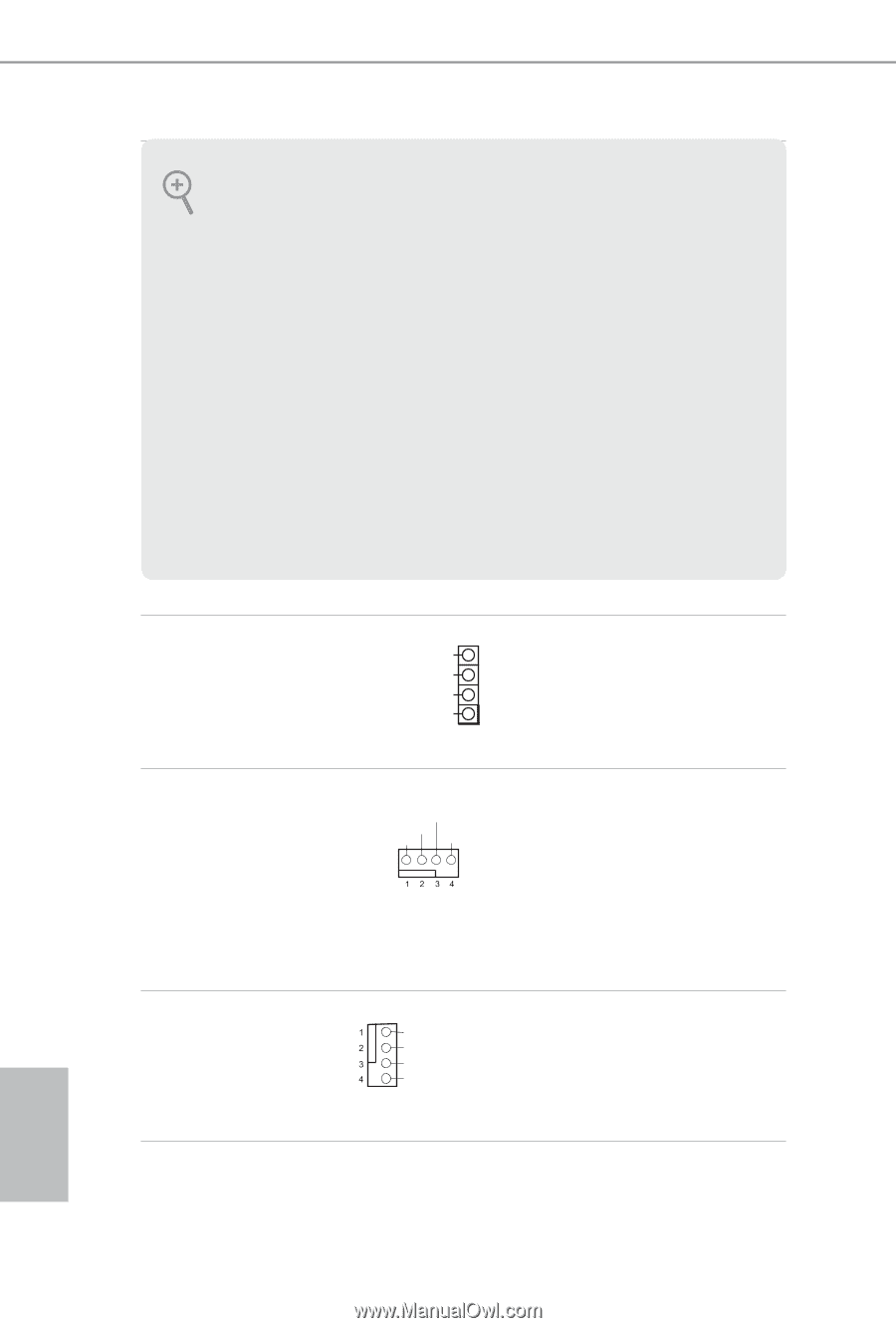
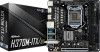
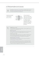
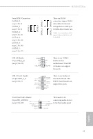
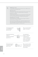
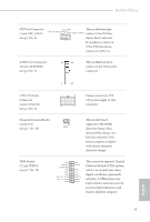
PWRBTN (Power Switch): Connect to the power switch on the chassis front panel. You may configure the way to turn off your system using the power switch. RESET (Reset Switch): Connect to the reset switch on the chassis front panel. Press the reset switch to restart the computer if the computer freezes and fails to perform a normal restart. PLED (System Power LED): Connect to the power status indicator on the chassis front panel. The LED is on when the system is operating. The LED keeps blinking when the system is in S1/S3 sleep state. The LED is off when the system is in S4 sleep state or powered off (S5). HDLED (Hard Drive Activity LED): Connect to the hard drive activity LED on the chassis front panel. The LED is on when the hard drive is reading or writing data. The front panel design may differ by chassis. A front panel module mainly consists of power switch, reset switch, power LED, hard drive activity LED, speaker and etc. When connecting your chassis front panel module to this header, make sure the wire assignments and the pin assignments are matched correctly. Chassis Speaker Header (4-pin SPEAKER1) (see p.7, No. 18) SPEAKER DUMMY DUMMY +5V 1 Please connect the chassis speaker to this header. Chassis/Water Pump Fan This motherboard Connector FAN_SPEED provides a 4-Pin water FAN_VOLTAGE_CONTROL GND FAN_SPEED_CONTROL (4-pin CHA_FAN1/WP) cooling chassis fan (see p.7, No. 2) connector. If you plan to connect a 3-Pin chassis water cooler fan, please connect it to Pin 1-3. Chassis Fan Connector (4-pin CHA_FAN2) (see p.7, No. 6) GND FAN_VOLTAGE_CONTROL FAN_SPEED FAN_SPEED_CONTROL Please connect fan cables to the fan connector and match the black wire to the ground pin. English 24
-
 1
1 -
2
-
3
-
4
-
5
-
6
-
7
-
8
-
9
-
10
-
11
-
12
-
13
-
14
-
15
-
16
-
17
-
18
-
19
-
20
-
21
-
22
-
23
-
24
-
 25
25 -
 26
26 -
 27
27 -
 28
28 -
 29
29 -
 30
30 -
 31
31 -
 32
32 -
 33
33 -
 34
34 -
 35
35 -
36
-
37
-
38
-
39
-
40
-
41
-
42
-
43
-
44
-
45
-
46
-
47
-
48
-
49
-
50
-
51
-
52
-
53
-
54
-
55
-
56
-
57
-
58
-
59
-
60
-
61
-
62
-
63
-
64
-
65
-
66
-
67
-
68
-
69
-
70
-
71
-
72
-
73
-
74
-
75
-
76
-
77
-
78
-
79
-
80
-
81
 |
 |