ASRock H410M-HVS R2.0 User Manual - Page 26
Front Panel Audio Header, USB 3.2 Gen1 Header
 |
View all ASRock H410M-HVS R2.0 manuals
Add to My Manuals
Save this manual to your list of manuals |
Page 26 highlights
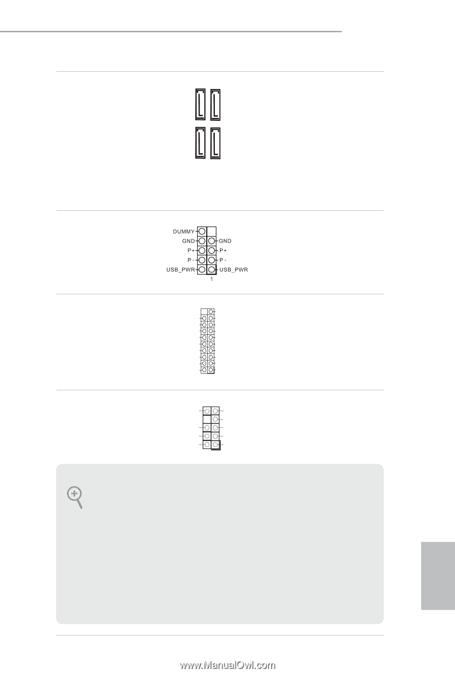
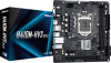
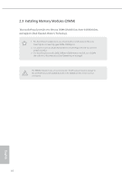
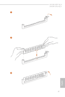
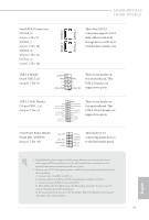
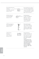
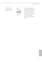
H410M-HDV R2.0 H410M-HVS R2.0 Serial ATA3 Connectors (SATA3_0: see p.6, 7, No. 9) (SATA3_1: see p.6, 7, No. 10) (SATA3_2: see p.6, 7, No. 11) (SATA3_3: see p.6, 7, No. 12) USB 2.0 Header (9-pin USB_5_6) (see p.6, 7, No. 8) SATA3_2 SATA3_0 SATA3_3 SATA3_1 These four SATA3 connectors support SATA data cables for internal storage devices with up to 6.0 Gb/s data transfer rate. There is one header on this motherboard. This USB 2.0 header can support two ports. USB 3.2 Gen1 Header (19-pin USB3_3_4) (see p.6, 7, No. 6) Vbus IntA_PA_SSRXIntA_PA_SSRX+ GND IntA_PA_SSTXIntA_PA_SSTX+ GND IntA_PA_DIntA_PA_D+ Vbus IntA_PB_SSRXIntA_PB_SSRX+ GND IntA_PB_SSTXIntA_PB_SSTX+ GND IntA_PB_DIntA_PB_D+ Dummy 1 There is one header on this motherboard. This USB 3.2 Gen1 header can support two ports. Front Panel Audio Header (9-pin HD_AUDIO1) (see p.6, 7, No. 16) OUT_RET MIC_RET PRESENCE# GND OUT2_L J_SENSE OUT2_R MIC2_R MIC2_L 1 This header is for connecting audio devices to the front audio panel. 1. High Definition Audio supports Jack Sensing, but the panel wire on the chassis must support HDA to function correctly. Please follow the instructions in our manual and chassis manual to install your system. 2. If you use an AC'97 audio panel, please install it to the front panel audio header by the steps below: A. Connect Mic_IN (MIC) to MIC2_L. B. Connect Audio_R (RIN) to OUT2_R and Audio_L (LIN) to OUT2_L. C. Connect Ground (GND) to Ground (GND). D. MIC_RET and OUT_RET are for the HD audio panel only. You don't need to connect them for the AC'97 audio panel. E. To activate the front mic, go to the "FrontMic" Tab in the Realtek Control panel and adjust "Recording Volume". 21 English
-
 1
1 -
2
-
3
-
4
-
5
-
6
-
7
-
8
-
9
-
10
-
11
-
12
-
13
-
14
-
15
-
16
-
17
-
18
-
19
-
20
-
 21
21 -
 22
22 -
 23
23 -
 24
24 -
 25
25 -
 26
26 -
 27
27 -
 28
28 -
 29
29 -
 30
30 -
 31
31 -
32
-
33
-
34
-
35
-
36
-
37
-
38
-
39
-
40
-
41
-
42
-
43
-
44
-
45
-
46
-
47
-
48
-
49
-
50
-
51
-
52
-
53
-
54
-
55
-
56
-
57
-
58
-
59
-
60
-
61
-
62
-
63
-
64
-
65
-
66
-
67
-
68
-
69
-
70
-
71
-
72
-
73
-
74
-
75
 |
 |