ASRock H55 Extreme3 User Manual - Page 24
Chassis and Power Fan Connectors
 |
View all ASRock H55 Extreme3 manuals
Add to My Manuals
Save this manual to your list of manuals |
Page 24 highlights
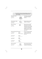
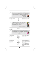
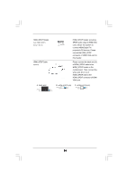
E. Enter BIOS Setup Utility. Enter Advanced Settings, and then select Chipset Configuration. Set the Front Panel Control option from [Auto] to [Enabled]. System Panel Header (9-pin PANEL1) (see p.11 No. 22) PLED+ PLEDPWRBTN# GND 1 DUMMY RESET# GND HDLEDHDLED+ This header accommodates several system front panel functions. Chassis Speaker Header (4-pin SPEAKER 1) (see p.11 No. 21) Power LED Header (3-pin PLED1) (see p.11 No. 24) 1 SPEAKER DUMMY DUMMY +5V 1 PLED- PLED+ PLED+ Please connect the chassis speaker to this header. Please connect the chassis power LED to this header to indicate system power status. The LED is on when the system is operating. The LED keeps blinking in S1 state. The LED is off in S3/S4 state or S5 state (power off). Chassis and Power Fan Connectors (4-pin CHA_FAN1) (see p.11 No. 9) GND +12V CHA_FAN_SPEED FAN_SPEED_CONTROL Please connect the fan cables to the fan connectors and match the black wire to the ground pin. (3-pin CHA_FAN2) (see p.11 No. 10) GND +12V CHA_FAN_SPEED (3-pin CHA_FAN3) (see p.11 No. 31) (3-pin PWR_FAN1) (see p.11 No. 2) CPU Fan Connector (4-pin CPU_FAN1) (see p.11 No. 3) GND +12V CHA_FAN_SPEED GND +12V PWR_FAN_SPEED 4 3 2 1 GND +12V CPU_FAN_SPEED FAN_SPEED_CONTROL Please connect a CPU fan cable to this connector and match the black wire to the ground pin. 24
-
 1
1 -
2
-
3
-
4
-
5
-
6
-
7
-
8
-
9
-
10
-
11
-
12
-
13
-
14
-
15
-
16
-
17
-
18
-
 19
19 -
 20
20 -
 21
21 -
 22
22 -
 23
23 -
 24
24 -
 25
25 -
 26
26 -
 27
27 -
 28
28 -
 29
29 -
30
-
31
-
32
-
33
-
34
-
35
-
36
-
37
-
38
-
39
-
40
-
41
-
42
-
43
-
44
-
45
-
46
-
47
-
48
-
49
-
50
-
51
-
52
-
53
-
54
-
55
-
56
-
57
-
58
-
59
 |
 |
