ASRock H55M User Manual - Page 27
Front Panel Audio Header
 |
View all ASRock H55M manuals
Add to My Manuals
Save this manual to your list of manuals |
Page 27 highlights
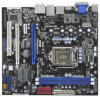
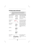
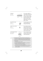
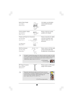
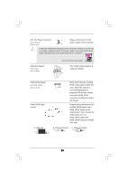
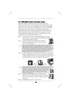
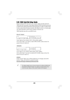
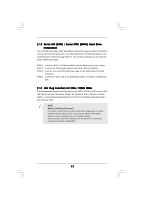
TPM Header (19-pin TPM1) (see p.12 No. 22) 1 PCICLK FRAME PCIRST# LAD3 +3V LAD0 NC +3VSB GND PWRDWN GND NC LAD2 LAD1 GND NC SERIRQ CLKRUN NC This connector supports a Trusted Platform Module (TPM) system, which can securely store keys, digital certificates, passwords, and data. A TPM system also helps enhance network security, protects digital identities, and ensures platform integrity. Infrared Module Header (5-pin IR1) (see p.12 No. 23) Chassis Intrusion Header (2-pin CI1) (see p.12 No. 21) IRTX +5VSB DUMMY 1 GND IRRX 1 GND Signal This header supports an optional wireless transmitting and receiving infrared module. This motherboard supports CASE OPEN detection feature that detects if the chassis cover has been removed. This feature requires a chassis with chassis intrusion detection design. Front Panel Audio Header (9-pin HD_AUDIO1) (see p.12 No. 31) GND PRESENCE# MIC_RET OUT_RET 1 OUT2_L J_SENSE OUT2_R MIC2_R MIC2_L This is an interface for front panel audio cable that allows convenient connection and control of audio devices. 1. High Definition Audio supports Jack Sensing, but the panel wire on the chassis must support HDA to function correctly. Please follow the instruction in our manual and chassis manual to install your system. 2. If you use AC'97 audio panel, please install it to the front panel audio header as below: A. Connect Mic_IN (MIC) to MIC2_L. B. Connect Audio_R (RIN) to OUT2_R and Audio_L (LIN) to OUT2_L. C. Connect Ground (GND) to Ground (GND). D. MIC_RET and OUT_RET are for HD audio panel only. You don't need to connect them for AC'97 audio panel. E. Enter BIOS Setup Utility. Enter Advanced Settings, and then select Chipset Configuration. Set the Front Panel Control option from [Auto] to [Enabled]. 27
-
 1
1 -
2
-
3
-
4
-
5
-
6
-
7
-
8
-
9
-
10
-
11
-
12
-
13
-
14
-
15
-
16
-
17
-
18
-
19
-
20
-
21
-
 22
22 -
 23
23 -
 24
24 -
 25
25 -
 26
26 -
 27
27 -
 28
28 -
 29
29 -
 30
30 -
 31
31 -
 32
32 -
33
-
34
-
35
-
36
-
37
-
38
-
39
-
40
-
41
-
42
-
43
-
44
-
45
-
46
-
47
-
48
-
49
-
50
-
51
-
52
-
53
-
54
-
55
-
56
-
57
-
58
 |
 |
