ASRock H570M-ITX/ac User Manual
ASRock H570M-ITX/ac Manual
 |
View all ASRock H570M-ITX/ac manuals
Add to My Manuals
Save this manual to your list of manuals |
ASRock H570M-ITX/ac manual content summary:
- ASRock H570M-ITX/ac | User Manual - Page 1
- ASRock H570M-ITX/ac | User Manual - Page 2
Version 1.0 Published January 2021 Copyright©2021 ASRock INC. All rights reserved. Copyright Notice: No part of this documentation may be reproduced, transcribed, transmitted, or translated in any language, in any form or by any means, except duplication of documentation by the purchaser for backup - ASRock H570M-ITX/ac | User Manual - Page 3
in, and licensed in accordance with, an enclosed license.txt file or other text or file. (e) Intel has no obligation to provide any support, technical assistance or updates for the Software. OWNERSHIP OF SOFTWARE AND COPYRIGHTS. Title to all copies of the Software remains with Intel or its - ASRock H570M-ITX/ac | User Manual - Page 4
ES OF ANY KIND WHETHER UNDER THIS AGREEMENT OR OTHERWISE, EVEN IF INTEL HAS BEEN ADVISED OF THE POSSIBILITY OF SUCH DAMAGES. LICENSE TO USE COMMENTS AND SUGGESTIONS. This Agreement does NOT obligate Licensee to provide Intel with comments or suggestions regarding the Software. However, if Licensee - ASRock H570M-ITX/ac | User Manual - Page 5
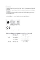
CE Warning This device complies with directive 2014/53/EU issued by the Commision of the European Community. This equipment complies with EU radiation exposure limits set forth for an uncontrolled environment. This equipment should be installed and operated with minimum distance 20cm between the - ASRock H570M-ITX/ac | User Manual - Page 6
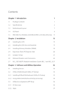
) 18 2.4 Expansion Slots (PCI Express Slot) 20 2.5 Jumpers Setup 21 2.6 Onboard Headers and Connectors 22 2.7 M.2_SSD (NGFF) Module Installation Guide (M2_1 and M2_2) 27 Chapter 3 Software and Utilities Operation 32 3.1 Installing Drivers 32 3.2 ASRock Motherboard Utility (A-Tuning) 33 - ASRock H570M-ITX/ac | User Manual - Page 7
3.3.3 BIOS & Drivers 40 3.3.4 Setting 41 3.4 Nahimic Audio 42 3.5 ASRock Polychrome SYNC 43 Chapter 4 UEFI SETUP UTILITY 46 4.1 Introduction 46 4.2 EZ Mode 47 4.3 Advanced Mode 48 4.3.1 UEFI Menu Bar 48 4.3.2 Navigation Keys 49 4.4 Main Screen 50 4.5 OC Tweaker Screen 51 4.6 - ASRock H570M-ITX/ac | User Manual - Page 8
- ASRock H570M-ITX/ac | User Manual - Page 9
Package Contents • ASRock H570M-ITX/ac Motherboard (Mini-ITX Form Factor) • ASRock H570M-ITX/ac Quick Installation Guide • ASRock H570M-ITX/ac Support CD • 2 x Serial ATA (SATA) Data Cables (Optional) • 1 x I/O Panel Shield • 2 x ASRock WiFi 2.4/5 GHz Antennas (Optional) • 2 x Screws for M.2 Sockets - ASRock H570M-ITX/ac | User Manual - Page 10
(XMP) 2.0 Expansion Slot 11th Gen Intel® CoreTM Processors • 1 x PCI Express 4.0 x16 Slot* 10th Gen Intel® CoreTM Processors • 1 x PCI Express 3.0 x16 Slot* * Supports NVMe SSD as boot disks • 1 x Vertical M.2 Socket (Key E) with the bundled WiFi- 802.11ac module (on the rear I/O) English 2 - ASRock H570M-ITX/ac | User Manual - Page 11
Auto Lip Sync, Deep Color (12bpc), xvYCC and HBR (High Bit Rate Audio) with HDMI 2.0 Port (Compliant HDMI monitor is required) • Supports HDCP 2.3 with HDMI 2.0 and DisplayPort 1.4 Ports • Supports 4K Ultra HD (UHD) playback with HDMI 2.0 and DisplayPort 1.4 Ports * 11th Gen Intel® CoreTM Processors - ASRock H570M-ITX/ac | User Manual - Page 12
User Customized Priority Control • Supports Wake-On-LAN • Supports Lightning/ESD Protection • Supports Energy Efficient Ethernet 802.3az • Supports PXE 1 x Gigabit LAN 10/100/1000 Mb/s (Intel® I219V): • Supports Wake-On-LAN • Supports Lightning/ESD Protection • Supports Energy Efficient Ethernet 802 - ASRock H570M-ITX/ac | User Manual - Page 13
chassis fan of maximum 1A (12W) fan power. • 1 x Chassis/Water Pump Fan Connector (4-pin) (Smart Fan Speed Control) * The Chassis/Water Pump Fan supports the water cooler fan of maximum 2A (24W) fan power. * CHA_FAN1/WP can auto detect if 3-pin or 4-pin fan is in use. • 1 x 24 pin - ASRock H570M-ITX/ac | User Manual - Page 14
BIOS Feature Hardware Monitor OS Certifications • AMI UEFI Legal BIOS with multilingual GUI support • ACPI 6.0 Compliant wake up events • SMBIOS 2.7 Support • CPU, CPU GT, VCCSA, DRAM, VPPM, VCCIN AUX, VC- CIO, VCCST Voltage Multi-adjustment • Fan Tachometer: CPU, Chassis, Chassis/Water Pump Fans • - ASRock H570M-ITX/ac | User Manual - Page 15
1.3 Motherboard Layout H570M-ITX/ac English 7 - ASRock H570M-ITX/ac | User Manual - Page 16
No. Description 1 Chassis/Waterpump Fan Connector (CHA_FAN1/WP) 2 CPU Fan Connector (CPU_FAN1) 3 ATX 12V Power Connector (ATX12V1) 4 2 x 288-pin DDR4 DIMM Slots (DDR4_A1, DDR4_B1) 5 ATX Power Connector (ATXPWR1) 6 USB 2.0 Header (USB_56) 7 USB 3.2 Gen1 Header (USB3_12) 8 SATA3 Connector (SATA3_1) 9 - ASRock H570M-ITX/ac | User Manual - Page 17
1.4 I/O Panel 1 H570M-ITX/ac 4 2 3 5 13 12 10 11 8 7 6 9 No. Description No. Description 1 DisplayPort 1.4 8 USB 3.2 Gen2 Type-A Port (USB31_TA_1) 2 LAN RJ-45 Port (Intel® I219V)* 9 USB 3.2 Gen2x2 Type-C Port (USB31_TC_1) 3 2.5G LAN RJ-45 Port (Dragon RTL8125BG)** 10 USB 2.0 Port - ASRock H570M-ITX/ac | User Manual - Page 18
** There are two LEDs on each LAN port. Please refer to the table below for the LAN port LED indications. ACT/LINK LED SPEED LED LAN Port Activity / Link LED Status Off Blinking On Description No Link Data Activity Link Speed LED Status Off Orange Green Description 10Mbps connection 100Mbps/ - ASRock H570M-ITX/ac | User Manual - Page 19
+ BT Module This motherboard comes with an exclusive WiFi 802.11 a/b/g/n/ac + BT v4.2 module (pre-installed on the rear I/O panel) that offers support for WiFi 802.11 a/b/ g/n/ac connectivity standards and Bluetooth v4.2. WiFi + BT module is an easy-touse wireless local area network (WLAN) adapter - ASRock H570M-ITX/ac | User Manual - Page 20
WiFi Antennas Installation Guide Step 1 Prepare the WiFi 2.4/5 GHz Antennas that come with the package. Step 2 Connect the two WiFi 2.4/5 GHz Antennas to the antenna connectors. Turn the antenna - ASRock H570M-ITX/ac | User Manual - Page 21
H570M-ITX/ac Chapter 2 Installation This is a Mini-ITX form factor motherboard. Before you install the motherboard, study the configuration of your chassis to ensure that the motherboard fits into it. Pre-installation Precautions Take note of the following precautions before you install motherboard - ASRock H570M-ITX/ac | User Manual - Page 22
2.1 Installing the CPU 1. Before you insert the 1200-Pin CPU into the socket, please check if the PnP cap is on the socket, if the CPU surface is unclean, or if there are any bent pins in the socket. Do not force to insert the CPU into the socket if above situation is found. Otherwise, the CPU will - ASRock H570M-ITX/ac | User Manual - Page 23
H570M-ITX/ac 3 4 5 15 English - ASRock H570M-ITX/ac | User Manual - Page 24
Please save and replace the cover if the processor is removed. The cover must be placed if you wish to return the motherboard for after service. 16 English - ASRock H570M-ITX/ac | User Manual - Page 25
2.2 Installing the CPU Fan and Heatsink H570M-ITX/ac 1 2 CPU_FAN 17 English - ASRock H570M-ITX/ac | User Manual - Page 26
2.3 Installing Memory Modules (DIMM) This motherboard provides two 288-pin DDR4 (Double Data Rate 4) DIMM slots, and supports Dual Channel Memory Technology. 1. For dual channel configuration, you always need to install identical (the same brand, speed, size and chip-type) DDR4 DIMM pairs. 2. - ASRock H570M-ITX/ac | User Manual - Page 27
H570M-ITX/ac 1 2 3 19 English - ASRock H570M-ITX/ac | User Manual - Page 28
2.4 Expansion Slots (PCI Express Slot) There is 1 PCI Express slot slot on the motherboard. Before installing an expansion card, please make sure that the power supply is switched off or the power cord is unplugged. Please read the documentation of the expansion card and make necessary hardware - ASRock H570M-ITX/ac | User Manual - Page 29
H570M-ITX/ac 2.5 Jumpers Setup The illustration shows how jumpers are setup. When the jumper cap is placed on the pins, the jumper is "Short". If no jumper cap is placed on the pins, the jumper is "Open". Clear CMOS Jumper (CLRMOS1) (see p.7, No. 17) 2-pin Jumper CLRMOS1 allows you to clear the - ASRock H570M-ITX/ac | User Manual - Page 30
2.6 Onboard Headers and Connectors Onboard headers and connectors are NOT jumpers. Do NOT place jumper caps over these headers and connectors. Placing jumper caps over the headers and connectors will cause permanent damage to the motherboard. System Panel Header (9-pin PANEL1) (see p.7, No. 13) - ASRock H570M-ITX/ac | User Manual - Page 31
No. 9) (SATA3_1: see p.7, No. 8) (SATA3_2: see p.7, No. 11) (SATA3_3: see p.7, No. 10) SATA3_3 SATA3_1 SATA3_2 SATA3_0 These four SATA3 connectors support SATA data cables for internal storage devices with up to 6.0 Gb/s data transfer rate. USB 2.0 Header (9-pin USB_56) (see p.7, No. 6) There is - ASRock H570M-ITX/ac | User Manual - Page 32
PWRBTN (Power Switch): Connect to the power switch on the chassis front panel. You may configure the way to turn off your system using the power switch. RESET (Reset Switch): Connect to the reset switch on the chassis front panel. Press the reset switch to restart the computer if the computer - ASRock H570M-ITX/ac | User Manual - Page 33
effects. Caution: Never install the RGB LED cable in the wrong orientation; otherwise, the cable may be damaged. * Please refer to page 43 for further instructions on this header. 25 English - ASRock H570M-ITX/ac | User Manual - Page 34
effects. Caution: Never install the Addressable LED cable in the wrong orientation; otherwise, the cable may be damaged. * Please refer to page 44 for further instructions on this header. English 26 - ASRock H570M-ITX/ac | User Manual - Page 35
-ITX/ac 2.7 M.2_SSD (NGFF) Module Installation Guide (M2_1 and M2_2) The M.2, also known as the Next Generation Form Factor (NGFF), is a small size and versatile card edge connector that aims to replace mPCIe and mSATA. The Hyper M.2 Socket (M2_1) supports M Key type 2280 M.2 PCI Express module up - ASRock H570M-ITX/ac | User Manual - Page 36
1 2 1 Step 3 Before installing a M.2 (NGFF) SSD module, please loosen the screws to remove the M.2 heatsink. *Please remove the protective films on the bottom side of the M.2 heatsink before you install a M.2 SSD module. A A 20o 2 1 2 Step 4 Align and gently insert the M.2 (NGFF) SSD module - ASRock H570M-ITX/ac | User Manual - Page 37
H570M-ITX/ac M.2_SSD (NGFF) Module Support List (M2_1) Vendor ADATA ADATA ADATA ADATA ADATA Apacer Corsair Intel -00ENX0 (NVME) WDS512G1X0C-00ENX0 (NVME) For the latest updates of M.2_SSD (NFGG) module support list, please visit our website for details: http://www.asrock.com English 29 - ASRock H570M-ITX/ac | User Manual - Page 38
M.2_SSD (NGFF) Module Support List (M2_2) Vendor ADATA ADATA ADATA ADATA ADATA ADATA ADATA ADATA ADATA ADATA Apacer Corsair Crucial Crucial Intel Intel Intel Kingston Kingston Kingston OCZ PATRIOT - ASRock H570M-ITX/ac | User Manual - Page 39
VSM100-240G-2280 VLM100-240G-2280B-RD WDS100T1B0B-00AS40 WDS240G1G0B-00RC30 WDS256G1X0C-00ENX0 (NVME) WDS512G1X0C-00ENX0 (NVME) For the latest updates of M.2_SSD (NFGG) module support list, please visit our website for details: http://www.asrock.com English 31 - ASRock H570M-ITX/ac | User Manual - Page 40
CD that comes with the motherboard contains necessary drivers and useful utilities that enhance the motherboard's features. Running The Support CD To begin using the support CD, insert the CD into your CD-ROM drive. The CD automatically displays the Main Menu if "AUTORUN" is enabled in your computer - ASRock H570M-ITX/ac | User Manual - Page 41
H570M-ITX/ac 3.2 ASRock Motherboard Utility (A-Tuning) ASRock Motherboard Utility (A-Tuning) is ASRock's multi purpose software suite with a new interface, more new features and improved utilities. 3.2.1 Installing ASRock Motherboard Utility (A-Tuning) ASRock Motherboard Utility (A-Tuning) can be - ASRock H570M-ITX/ac | User Manual - Page 42
OC Tweaker Configurations for overclocking the system. System Info View information about the system. *The System Browser tab may not appear for certain models. 34 English - ASRock H570M-ITX/ac | User Manual - Page 43
H570M-ITX/ac FAN-Tastic Tuning Configure up to five different fan speeds using the graph. The fans will automatically shift to the next speed level when the assigned temperature is met. Settings Configure ASRock ASRock Motherboard Utility (A-Tuning). Click to select "Auto run at Windows Startup" if - ASRock H570M-ITX/ac | User Manual - Page 44
Shop is an online store for purchasing and downloading software applications for your ASRock computer. You can quickly and easily install various apps and support utilities. With ASRock Live Update & APP Shop, you can optimize your system and keep your motherboard up to date simply with a few clicks - ASRock H570M-ITX/ac | User Manual - Page 45
H570M-ITX/ac 3.3.2 Apps When the "Apps" tab is selected, you will see all the available apps on screen for you to download. Installing an App Step 1 Find the app you want to install. The most recommended app appears on the left side of the screen. The other various apps are shown on the right. - ASRock H570M-ITX/ac | User Manual - Page 46
Step 3 If you want to install the app, click on the red icon to start downloading. Step 4 When installation completes, you can find the green "Installed" icon appears on the upper right corner. English To uninstall it, simply click on the trash can icon . *The trash icon may not appear for - ASRock H570M-ITX/ac | User Manual - Page 47
H570M-ITX/ac Upgrading an App You can only upgrade the apps you have already installed. When there is an available new version for your app, you will find the mark of "New Version" appears below the installed app icon. Step 1 Click on the app icon to see more details. Step 2 Click on the yellow - ASRock H570M-ITX/ac | User Manual - Page 48
3.3.3 BIOS & Drivers Installing BIOS or Drivers When the "BIOS & Drivers" tab is selected, you will see a list of recommended or critical updates for the BIOS or drivers. Please update them all soon. Step 1 Please check the item information before update. Click on Step 2 to see more details. - ASRock H570M-ITX/ac | User Manual - Page 49
H570M-ITX/ac 3.3.4 Setting In the "Setting" page, you can change the language, select the server location, and determine if you want to automatically run the ASRock Live Update & APP Shop on Windows startup. 41 English - ASRock H570M-ITX/ac | User Manual - Page 50
3.4 Nahimic Audio Nahimic audio software provides an incredible high definition sound technology which boosts the audio and voice performance of your system. Nahimic Audio interface is composed of four tabs: Audio, Microphone, Sound Tracker and Settings. There are four functions in Nahimic audio : - ASRock H570M-ITX/ac | User Manual - Page 51
do so may cause damages to motherboard components. 1. Please note that the RGB LED strips do not come with the package. 2. The RGB LED header supports standard 5050 RGB LED strip (12V/G/R/B), with a maximum power rating of 3A (12V) and length within 2 meters. 43 English - ASRock H570M-ITX/ac | User Manual - Page 52
do so may cause damages to motherboard components. 1. Please note that the RGB LED strips do not come with the package. 2. The RGB LED header supports WS2812B addressable RGB LED strip (5V/Data/ GND), with a maximum power rating of 3A (5V) and length within 2 meters. 44 English - ASRock H570M-ITX/ac | User Manual - Page 53
H570M-ITX/ac ASRock Polychrome SYNC Utility Now you can adjust the RGB LED color through the ASRock Polychrome SYNC Utility. Download this utility from the ASRock Live Update & APP Shop and start coloring your PC style your way! Drag the tab to customize your preference. Toggle on/off the RGB LED - ASRock H570M-ITX/ac | User Manual - Page 54
Chapter 4 UEFI SETUP UTILITY 4.1 Introduction This section explains how to use the UEFI SETUP UTILITY to configure your system. You may run the UEFI SETUP UTILITY by pressing or right after you power on the computer, otherwise, the Power-On-Self-Test (POST) will continue with its test - ASRock H570M-ITX/ac | User Manual - Page 55
H570M-ITX/ac 4.2 EZ Mode The EZ Mode screen appears when you enter the BIOS setup program by default. EZ mode is a dashboard which contains multiple readings of the system's current status. You can check the most crucial information of your system, such as CPU speed, DRAM frequency, SATA - ASRock H570M-ITX/ac | User Manual - Page 56
4.3 Advanced Mode The Advanced Mode provides more options to configure the BIOS settings. Refer to the following sections for the detailed configurations. To access the EZ Mode, press or click the "EZ Mode" button at the upper right corner of the screen. 4.3.1 UEFI Menu Bar The top of the - ASRock H570M-ITX/ac | User Manual - Page 57
H570M-ITX/ac 4.3.2 Navigation Keys Use < > key or < > key to choose among the selections on the menu bar, and use < > key or < > key to move the cursor up or down to select items, then press to get into the sub screen. You can also use the mouse to click your required item. Please check the - ASRock H570M-ITX/ac | User Manual - Page 58
4.4 Main Screen When you enter the UEFI SETUP UTILITY, the Main screen will appear and display the system overview. The availability and location of BIOS settings can be different for different models and BIOS versions. My Favorite Display your collection of BIOS items. Press F5 to add/remove your - ASRock H570M-ITX/ac | User Manual - Page 59
4.5 OC Tweaker Screen In the OC Tweaker screen, you can set up overclocking features. H570M-ITX/ac Because the UEFI software is constantly being updated, the following UEFI setup screens and descriptions are for reference purpose only, and they may not exactly match what you see on your screen. - ASRock H570M-ITX/ac | User Manual - Page 60
maximum possible ratio for SSE workloads. CPU Cache Ratio The CPU Internal Bus Speed Ratio. The maximum should be the same as the CPU Ratio. GT Frequency Configure the frequency of the integrated GPU. BCLK Frequency The CPU speed is determined by the CPU Ratio multiplied with the BCLK. Increasing - ASRock H570M-ITX/ac | User Manual - Page 61
state. Intel Thermal Velocity Boost Voltage Optimizations This service controls thermal based voltage optimizations for processors that for CMLS 35W/65W/125W skus. This item is only supported with processors with Config TDP support. Long Duration Power Limit Configure Package Power Limit 1 in watts - ASRock H570M-ITX/ac | User Manual - Page 62
System Agent Current Limit Configure the current limit of the system agent. A lower limit can protect the CPU and save power, while a higher limit may improve performance. GT Current Limit Configure the current limit of the GT slice. A lower limit can protect the CPU and save power, while a higher - ASRock H570M-ITX/ac | User Manual - Page 63
H570M-ITX/ac in response. RAS# to CAS# Delay and Row Precharge (tRCDtRP) RAS# to CAS# Delay : The number of clock cycles required between the opening of a row of memory and accessing columns within it. Row Precharge: The number of clock cycles required between the issuing of the precharge command - ASRock H570M-ITX/ac | User Manual - Page 64
Read to Precharge (tRTP) The number of clocks that are inserted between a read command to a row precharge command to the same rank. Four Activate Window (tFAW) The time window in which four activates are allowed the same rank. CAS Write Latency (tCWL) Configure CAS Write Latency. Third Timing tREFI - ASRock H570M-ITX/ac | User Manual - Page 65
tRDWR_dr Configure between module read to write delay. tRDWR_dd Configure between module read to write delay. tWRRD_sg Configure between module write to read delay. tWRRD_dg Configure between module write to read delay. tWRRD_dr Configure between module write to read delay. tWRRD_dd Configure - ASRock H570M-ITX/ac | User Manual - Page 66
termination resistors' WR for channel B1. ODT NOM (A1) Use this to change ODT (CH A1) Auto/Manual settings. The default is [Auto]. ODT NOM (B1) Use this to change ODT (CH B1) Auto/Manual settings. The default is [Auto]. ODT PARK (A1) Configure the memory on die termination resistors' PARK for - ASRock H570M-ITX/ac | User Manual - Page 67
H570M-ITX/ac Advanced Setting ASRock Timing Optimization Configure the fast path through the MRC. ASRock Second Timing Optimization Configure the second fast path through the MRC. Memory Training Mode Configure the Training Memory Mode. Realtime Memory Timing Configure the realtime memory timings. [ - ASRock H570M-ITX/ac | User Manual - Page 68
CPU GT Load-Line Calibration GT Load-Line Calibration helps prevent integrated GPU voltage droop when the system is under heavy load. VCCSA Voltage Configure the voltage for the VCCSA. VCCSA Load-Line Calibration VCCSA Load-Line Calibration helps prevent integrated VCCSA voltage droop when the - ASRock H570M-ITX/ac | User Manual - Page 69
H570M-ITX/ac Ring PLL Voltage Default is 0.900V. Each step is 0.0175V. Adding 9~15 steps will help CPU PLL to lock internal clock during High frequency under Ln2 cooling. For Example: 1.0575V ~ 1.1625V will be proper value. But the voltage level will be different on each processor. User has to find - ASRock H570M-ITX/ac | User Manual - Page 70
Load User UEFI Setup Profile from Disk You can load previous saved profile from the disk. 62 English - ASRock H570M-ITX/ac | User Manual - Page 71
UEFI setup utility. Full HD UEFI When [Auto] is selected, the resolution will be set to 1920 x 1080 if the monitor supports Full HD resolution. If the monitor does not support Full HD resolution, then the resolution will be set to 1024 x 768. When [Disable] is selected, the resolution will be set - ASRock H570M-ITX/ac | User Manual - Page 72
on threaded software is improved. Active Processor Cores Select the number of cores to enable in each processor package. CPU C States Support Enable CPU C States Support for power saving. It is recommended to keep C6 and C7 all enabled for better power saving. Enhanced Halt State (C1E) Enable - ASRock H570M-ITX/ac | User Manual - Page 73
. This is applicable for Big Core only. Intel AVX-512 Enable/Disable the Intel AVX-512 (a.k.a. AVX3) Instructions. This is applicable for Big Core only. Intel Virtualization Technology Intel Virtualization Technology allows a platform to run multiple operating systems and applications in independent - ASRock H570M-ITX/ac | User Manual - Page 74
primary VGA. Above 4G Decoding Enable or disable 64bit capable Devices to be decoded in Above 4G Address Space (only if the system supports 64 bit PCI decoding). VT-d Intel® Virtualization Technology for Directed I/O helps your virtual machine monitor better utilize hardware by improving application - ASRock H570M-ITX/ac | User Manual - Page 75
This option enables/disables the control of ASPM on CPU side of the DMI Link. PCH DMI ASPM Support This option enables/disables the ASPM support for all PCH DMI devices. Share Memory Configure the size of memory that is allocated to the integrated graphics processor when the system boots up. - ASRock H570M-ITX/ac | User Manual - Page 76
Use this item to enable or disable the onboard WAN device. WAN Radio Enable/disable the WiFi module's connectivity. Bluetooth Enable/disable the Bluetooth connectivity. Deep Sleep Configure deep sleep mode for power saving when the computer is shut down. Restore on AC/Power Loss Select the power - ASRock H570M-ITX/ac | User Manual - Page 77
Enable/disable the SATA controllers. SATA Mode Selection AHCI: Supports new features that improve performance. RAID: Combine multiple disk power state during periods of inactivity to save power. It is only supported by AHCI mode. Hard Disk S.M.A.R.T. S.M.A.R.T stands for Self-Monitoring, Analysis - ASRock H570M-ITX/ac | User Manual - Page 78
to RAM Select disable for ACPI suspend type S1. It is recommended to select auto for ACPI S3 power saving. PS/2 Keyboard S4/S5 Wakeup Support Allow the system to be waked up by a PS/2 Keyboard in S4/S5. PCIE Devices Power On Allow the system to be waked up by - ASRock H570M-ITX/ac | User Manual - Page 79
4.6.5 USB Configuration H570M-ITX/ac XHCI Hand-off This is a workaround for OSes without XHCI hand-off support. The XHCI ownership change should be claimed by XHCI driver. English 71 - ASRock H570M-ITX/ac | User Manual - Page 80
4.6.6 Trusted Computing Security Device Support Enable or disable BIOS support for security device. 72 English - ASRock H570M-ITX/ac | User Manual - Page 81
Select LED lighting color. UEFI Tech Service Contact ASRock Tech Service if you are having trouble with your PC. Please setup network configuration before using UEFI Tech Service. Easy RAID Installer Easy RAID Installer helps you to copy the RAID driver from the support CD to your USB storage device - ASRock H570M-ITX/ac | User Manual - Page 82
UEFI. Internet Flash - DHCP (Auto IP), Auto ASRock Internet Flash downloads and updates the latest UEFI firmware version from our servers for you. Please setup network configuration before using Internet Flash. *For BIOS backup and recovery purpose, it is recommended to plug in your USB pen drive - ASRock H570M-ITX/ac | User Manual - Page 83
H570M-ITX/ac 4.8 Hardware Health Event Monitoring Screen This section allows you to monitor the status of the hardware on your system, including the parameters of the CPU temperature, motherboard temperature, fan speed and voltage. Fan Tuning Measure Fan Min Duty Cycle. Fan-Tastic Tuning Select a - ASRock H570M-ITX/ac | User Manual - Page 84
Chassis Fan 1 Control Mode Select PWM mode or DC mode for Chassis Fan 1. Chassis Fan 1 Setting Select a fan mode for Chassis Fan 1, or choose Customize to set 5 CPU temperatures and assign a respective fan speed for each temperature. Chassis Fan 1 Temp Source Select a fan temperature source for - ASRock H570M-ITX/ac | User Manual - Page 85
settings in the UEFI Setup Utility. Leave it blank and press enter to remove the password. Secure Boot Use this item to enable or disable support for Secure Boot. Intel(R) Platform Trust Technology Enable/disable Intel PTT in ME. Disable this option to use discrete TPM Module. 77 English - ASRock H570M-ITX/ac | User Manual - Page 86
priority. Fast Boot Fast Boot minimizes your computer's boot time. In fast mode you may not boot from an USB storage device. The VBIOS must support UEFI GOP if you are using an external graphics card. Please notice that Ultra Fast mode will boot so fast that the only way to - ASRock H570M-ITX/ac | User Manual - Page 87
If the computer fails to boot for a number of times the system automatically restores the default settings. CSM (Compatibility Support Module) CSM Enable to launch the Compatibility Support Module. Please do not disable unless you're running a WHCK test. Launch PXE OpROM Policy Select UEFI only to - ASRock H570M-ITX/ac | User Manual - Page 88
Select UEFI only to run those that support UEFI option ROM only. Select Legacy only to run those that support legacy option ROM only. Select Do not launch to not execute both legacy and UEFI option ROM. Other PCI Device ROM Priority For PCI devices - ASRock H570M-ITX/ac | User Manual - Page 89
4.11 Exit Screen H570M-ITX/ac Save Changes and Exit When you select this option the following message, "Save configuration changes and exit setup?" will pop out. Select [OK] to save changes and exit the UEFI SETUP UTILITY. Discard Changes and Exit When you select this option the following message, - ASRock H570M-ITX/ac | User Manual - Page 90
to visit ASRock's website at http://www.asrock.com; or you may contact your dealer for further information. For technical questions, please submit a support request form at https://event.asrock.com/tsd.asp ASRock Incorporation 2F., No.37, Sec. 2, Jhongyang S. Rd., Beitou District, Taipei City 112 - ASRock H570M-ITX/ac | User Manual - Page 91
DECLARATION OF CONFORMITY Per FCC Part 2 Section 2.1077(a) Responsible Party Name: ASRock Incorporation Address: 13848 Magnolia Ave, Chino, CA91710 Phone/Fax No: +1-909-590-8308/+1-909-590-1026 hereby declares that the product Product Name : Motherboard Model Number : H570M-ITX/ac Conforms to the - ASRock H570M-ITX/ac | User Manual - Page 92
EU Declaration of Conformity For the following equipment: Motherboard (Product Name) H570M-ITX/ac / ASRock (Model Designation / Trade Name) ASRock Incorporation (Manufacturer Name) 2F., No.37, Sec. 2, Jhongyang S. Rd., Beitou District, Taipei City 112, Taiwan (R.O.C.) (Manufacturer Address) ڛ
-
 1
1 -
 2
2 -
 3
3 -
 4
4 -
 5
5 -
 6
6 -
 7
7 -
8
-
9
-
10
-
11
-
12
-
13
-
14
-
15
-
16
-
17
-
18
-
19
-
20
-
21
-
22
-
23
-
24
-
25
-
26
-
27
-
28
-
29
-
30
-
31
-
32
-
33
-
34
-
35
-
36
-
37
-
38
-
39
-
40
-
41
-
42
-
43
-
44
-
45
-
46
-
47
-
48
-
49
-
50
-
51
-
52
-
53
-
54
-
55
-
56
-
57
-
58
-
59
-
60
-
61
-
62
-
63
-
64
-
65
-
66
-
67
-
68
-
69
-
70
-
71
-
72
-
73
-
74
-
75
-
76
-
77
-
78
-
79
-
80
-
81
-
82
-
83
-
84
-
85
-
86
-
87
-
88
-
89
-
90
-
91
-
92
 |
 |
