ASRock H61 Pro Quick Installation Guide - Page 2
Motherboard Layout
 |
View all ASRock H61 Pro manuals
Add to My Manuals
Save this manual to your list of manuals |
Page 2 highlights
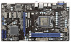
Motherboard Layout 1 17.3cm (6.8 in) 2 3 4 Designed in Taipei CPU_FAN1 ATX12V1 PS2 Mouse PS2 Keyboard VGA1 30.5cm (12.0 in) DX10.1 DDR3 HDMI1 Dual Channel DDR3_A1 (64 bit, 240-pin module) DDR3_B1 (64 bit, 240-pin module) USB 2.0 T: USB0 B: USB1 USB 2.0 T: USB2 B: USB3 USB 2.0 T: USB4 Top: 5 B: USB5 RJ-45 AT X P W R 1 Top: LINE IN Center: FRONT Bottom: MIC IN 27 PWR_FAN1 H61 Pro LAN PHY 26 PCIE1 HDMI 1.4a PCI Express 2.0 25 PCIE2 CHA_FAN1 6 24 23 22 21 Super I/O PCIE3 RoHS PCIE4 ErP/EuP Ready Intel H61 32Mb BIOS 7 8 AUDIO CODEC HD_AUDIO1 1 PCIE5 CMOS Battery PCIE6 COM1 1 USB6_7 1 USB8_9 1 PLED PWRBTN 1 HDLED RESET PANEL1 SATA2_0 SATA2_1 CLRCMOS1 1 1 SATA2_2 SPEAKER1 SATA2_3 IR1 1 9 10 11 12 20 19 18 17 16 15 14 13 1 1155-Pin CPU Socket 15 SATA2 Connector (SATA2_1, Blue) 2 CPU Fan Connector (CPU_FAN1) 16 System Panel Header (PANEL1, White) 3 ATX 12V Power Connector (ATX12V1) 17 USB 2.0 Header (USB8_9, Blue) 4 2 x 240-pin DDR3 DIMM Slots 18 USB 2.0 Header (USB6_7, Blue) (Dual Channel: DDR3_A1, DDR3_B1, Blue) 19 COM Port Header (COM1) 5 ATX Power Connector (ATXPWR1) 20 Front Panel Audio Header 6 Chassis Fan Connector (CHA_FAN1) (HD_AUDIO1, White) 7 32Mb SPI Flash 21 PCI Express 2.0 x1 Slot (PCIE6, White) 8 Intel H61 Chipset 22 PCI Express 2.0 x1 Slot (PCIE5, White) 9 Clear CMOS Jumper (CLRCMOS1) 23 PCI Express 2.0 x1 Slot (PCIE4, White) 10 Chassis Speaker Header (SPEAKER 1, White) 24 PCI Express 2.0 x1 Slot (PCIE3, White) 11 SATA2 Connector (SATA2_2, Blue) 25 PCI Express 2.0 x16 Slot (PCIE2, Blue) 12 SATA2 Connector (SATA2_0, Blue) 26 PCI Express 2.0 x1 Slot (PCIE1, White) 13 Infrared Module Header (IR1) 27 Power Fan Connector (PWR_FAN1) 14 SATA2 Connector (SATA2_3, Blue) 2 ASRock H61 Pro Motherboard English
-
 1
1 -
 2
2 -
 3
3 -
 4
4 -
 5
5 -
 6
6 -
 7
7 -
 8
8 -
9
-
10
-
11
-
12
-
13
-
14
-
15
-
16
-
17
-
18
-
19
-
20
-
21
-
22
-
23
-
24
-
25
-
26
-
27
-
28
-
29
-
30
-
31
-
32
-
33
-
34
-
35
-
36
-
37
-
38
-
39
-
40
-
41
-
42
-
43
-
44
-
45
-
46
-
47
-
48
-
49
-
50
-
51
-
52
-
53
-
54
-
55
-
56
-
57
-
58
-
59
-
60
-
61
-
62
-
63
-
64
-
65
-
66
-
67
-
68
 |
 |
