ASRock H61M-PS2 User Manual
ASRock H61M-PS2 Manual
 |
View all ASRock H61M-PS2 manuals
Add to My Manuals
Save this manual to your list of manuals |
ASRock H61M-PS2 manual content summary:
- ASRock H61M-PS2 | User Manual - Page 1
H61M-PS2 User Manual Version 1.0 Published March 2012 Copyright©2012 ASRock INC. All rights reserved. 1 - ASRock H61M-PS2 | User Manual - Page 2
purchaser for backup purpose, without written consent of ASRock Inc. Products and corporate names appearing in this manual may or may not be registered trademarks or copyrights , USA ONLY The Lithium battery adopted on this motherboard contains Perchlorate, a toxic substance controlled in Perchlorate - ASRock H61M-PS2 | User Manual - Page 3
5 1.1 Package Contents 5 1.2 Specifications 6 1.3 Motherboard Layout 12 1.4 I/O Panel 13 2 Installation 14 2.1 / SATAII HDDs 27 2.12 SATA / SATAII HDD Hot Plug Feature and Operation Guide 28 2.13 Driver Installation Guide 30 2.14 Installing Windows® 7 / 7 64-bit / VistaTM / VistaTM - ASRock H61M-PS2 | User Manual - Page 4
Health Event Monitoring Screen 49 3.6 Boot Screen 50 3.7 Security Screen 51 3.8 Exit Screen 52 4 Software Support 53 4.1 Install Operating System 53 4.2 Support CD Information 53 4.2.1 Running Support CD 53 4.2.2 Drivers Menu 53 4.2.3 Utilities Menu 53 4.2.4 Contact Information 53 4 - ASRock H61M-PS2 | User Manual - Page 5
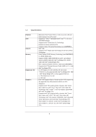
fic information about the model you are using. www.asrock.com/support/index.asp 1.1 Package Contents ASRock H61M-PS2 Motherboard (Micro ATX Form Factor: 9.6-in x 7.8-in, 24.4 cm x 19.8 cm) ASRock H61M-PS2 Quick Installation Guide ASRock H61M-PS2 Support CD 2 x Serial ATA (SATA) Data Cables (Optional - ASRock H61M-PS2 | User Manual - Page 6
Sync Video 2.0, Intel® InTruTM 3D, Intel® Clear Video HD Technology, Intel® InsiderTM, Intel® HD Graphics 2500/4000 with Intel® Ivy Bridge CPU - Supports Intel® HD Graphics Built-in Visuals: Intel® Quick Sync Video, Intel® InTruTM 3D, Intel® Clear Video HD Technology, Intel® HD Graphics 2000/3000 - ASRock H61M-PS2 | User Manual - Page 7
8 pin 12V power connector - Front panel audio connector - 2 x USB 2.0 headers (support 4 USB 2.0 ports) - 32Mb AMI BIOS - AMI UEFI Legal BIOS with GUI support - Supports "Plug and Play" - ACPI 1.1 Compliance Wake Up Events - Supports jumperfree - SMBIOS 2.3.1 Support - CPU Core, IGPU, DRAM, PCH, CPU - ASRock H61M-PS2 | User Manual - Page 8
* For detailed product information, please visit our website: http://www.asrock.com WARNING Please realize that there is a certain risk involved with overclocking, including adjusting the setting in the BIOS, applying Untied Overclocking Technology, or using the third-party - ASRock H61M-PS2 | User Manual - Page 9
This motherboard supports Dual Channel Memory Technology. Before you implement Dual Channel Memory Technology, make sure to read the installation guide of /iPod/iPad Touch, ASRock has prepared a wonderful solution for you - ASRock APP Charger. Simply installing the APP Charger driver, it makes your - ASRock H61M-PS2 | User Manual - Page 10
driver installed, you can easily enjoy the marvelous charging experience than ever. ASRock website: http://www.asrock a more personal Internet experience. ASRock motherboards are exclusively equipped with the You can watch Youtube HD video and download files simultaneously. Real-Time Analysis of Your - ASRock H61M-PS2 | User Manual - Page 11
, Socket LGA 775, LGA 1155 and LGA 1156. Please be noticed that not all the 775 and 1156 CPU Fan can be used. 16. ASRock XFast RAM is not supported by 00W in off mode condition. To meet EuP standard, an EuP ready motherboard and an EuP ready power supply are required. According to Intel's suggestion - ASRock H61M-PS2 | User Manual - Page 12
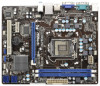
Fast USB X Top: LINE IN Center: FRONT Bottom: MIC IN H61M-PS2 ErP/EuP Ready 23 22 AUDIO CODEC 21 20 PCIE1 Super I/O PCIE2 RoHS CMOS Battery PCI1 IR1 1 CHA_FAN1 CLRCMOS1 1 USB6_7 1 Intel H61 32Mb BIOS SATA2_0 USB4_5 1 PANEL1 PLED PWRBTN 1 HDLED RESET SATA2_1 SATA2_2 SPEAKER1 - ASRock H61M-PS2 | User Manual - Page 13
(USB23) 7 USB 2.0 Ports (USB01) 8 VGA Port 9 COM Port 10 PS/2 Keyboard Port (Purple) * There are two LED next to the LAN port. Please audio cable to the front panel audio header. After restarting your computer, you will find "VIA HD Audio Deck" tool on your system. Please follow below instructions - ASRock H61M-PS2 | User Manual - Page 14
Precautions Take note of the following precautions before you install motherboard components or change any motherboard settings. 1. Unplug the power cord from the wall socket before touching any component. 2. To avoid damaging the motherboard components due to static electricity, NEVER place your - ASRock H61M-PS2 | User Manual - Page 15
Socket Body 1155-Pin Socket Overview Before you insert the 1155-Pin CPU into the socket, please check if the CPU surface is unclean or if there is any bent pin on the socket. Do not force to insert the CPU into the socket 2. This cap must be placed if returning the motherboard for after service. 15 - ASRock H61M-PS2 | User Manual - Page 16
Heat Sink) up. Locate Pin1 and the two orientation key notches. orientation key notch alignment key Pin1 Pin1 orientation key notch 1155-Pin CPU alignment key 1155-Pin Socket For proper inserting, please ensure to match the two orientation key notches of the CPU with the two alignment keys of - ASRock H61M-PS2 | User Manual - Page 17
Heatsink This motherboard is equipped with 1155-Pin socket that supports Intel 1155-Pin CPU. instruction manuals of your CPU fan and heatsink. Below is an example to illustrate the installation of the heatsink for 1155-Pin CPU. Step 1. Apply thermal interface material onto center of IHS on the socket - ASRock H61M-PS2 | User Manual - Page 18
2.5 Installation of Memory Modules (DIMM) This motherboard provides two 240-pin DDR3 (Double Data Rate 3) DIMM slots, and supports Dual Channel Memory Technology. For dual channel configuration, you always need to install two identical (the same brand, speed, size and chiptype) memory modules in - ASRock H61M-PS2 | User Manual - Page 19
width cards, such as Gigabit LAN card, SATA2 card, etc. Only PCIE1 slot supports Gen 3 speed. To run the PCI Express in Gen 3 speed, please install start the installation. Step 2. Remove the system unit cover (if your motherboard is already installed in a chassis). Step 3. Remove the bracket facing - ASRock H61M-PS2 | User Manual - Page 20
Monitor Feature This motherboard supports multi monitor upgrade. With the internal VGA output support and external add- is inserted to this motherboard. 4. Install the onboard VGA driver and the add-on PCI Express VGA card driver to your system. If you have installed the drivers already, there is no - ASRock H61M-PS2 | User Manual - Page 21
D. Click "Extend my Windows desktop onto this monitor". E. Right-click the display icon and select "Attached", if necessary. F. Set the "Screen Resolution" and "Color Quality" as appropriate for the second monitor. Click "Apply" or "OK" to apply these new values. G. Repeat steps C through E for the - ASRock H61M-PS2 | User Manual - Page 22
clear the CMOS when you just finish updating the BIOS, you must boot up the system first, and then shut it down before you do the clear-CMOS action. Please be noted that the password, date, time, user default profile, 1394 GUID and MAC address will be cleared only if the - ASRock H61M-PS2 | User Manual - Page 23
connected to the SATA / SATAII hard disk or the SATAII connector on this motherboard. Besides four default USB 2.0 ports on the I/O panel, there are two USB 2.0 headers on this motherboard. Each USB 2.0 header can support two USB 2.0 ports. Infrared Module Header (5-pin IR1) (see p.12 No. 19) IRTX - ASRock H61M-PS2 | User Manual - Page 24
cable that allows convenient connection and control of audio devices. 1. High Definition Audio supports Jack Sensing, but the panel wire on the chassis must support HDA to function correctly. Please follow the instruction in our manual and chassis manual to install your system. 2. If you use AC - ASRock H61M-PS2 | User Manual - Page 25
GND 1 2 3 4 Please connect the CPU fan cable to the connector and match the black wire to the ground pin. Though this motherboard provides 4-Pin CPU fan (Quiet Fan) support, the 3-Pin CPU fan still can work successfully even without the fan speed control function. If you plan to connect the 3-Pin - ASRock H61M-PS2 | User Manual - Page 26
ATX 12V Power Connector (8-pin ATX12V1) (see p.12 No. 4) 8 5 4 1 Please connect an ATX 12V power supply to this connector. Though this motherboard provides 8-pin ATX 12V power connector, it can still work if you adopt a traditional 4-pin ATX 12V power supply. To use the 4-pin ATX power - ASRock H61M-PS2 | User Manual - Page 27
ATAII (SATAII) Hard Disks Installation This motherboard adopts Intel® H61 chipset that supports Serial ATA (SATA) / Serial ATAII (SATAII) hard disks. You may install SATA / SATAII hard disks on this motherboard for internal storage devices. This section will guide you to install the SATA / SATAII - ASRock H61M-PS2 | User Manual - Page 28
is installed into system properly. The latest SATA / SATAII driver is available on our support website: www.asrock.com 4. Make sure to use the SATA power cable & data cable, which are from our motherboard package. 5. Please follow below instructions step by step to reduce the risk of HDD crash or - ASRock H61M-PS2 | User Manual - Page 29
the power supply 1x4-pin cable. Connect SATA data cable to the motherboard's SATAII connector. SATA power cable 1x4-pin power connector (White) attention, before you process the Hot Unplug: Please do follow below instruction sequence to process the Hot Unplug, improper procedure will cause the - ASRock H61M-PS2 | User Manual - Page 30
2.13 Driver Installation Guide To install the drivers to your system, please insert the support CD to your optical drive first. Then, the drivers compatible to your system can be auto-detected and listed on the support CD driver page. Please follow the order from up to bottom side to install those - ASRock H61M-PS2 | User Manual - Page 31
beginning of Windows® setup, press F6 to install a third-party AHCI driver. When prompted, insert the SATA / SATAII driver diskette containing the Intel® AHCI driver. After reading the floppy disk, the driver will be presented. Select the driver to install according to the mode you choose and the OS - ASRock H61M-PS2 | User Manual - Page 32
Chapter 3: UEFI SETUP UTILITY 3.1 Introduction This section explains how to use the UEFI SETUP UTILITY to configure your system. The UEFI chip on the motherboard stores the UEFI SETUP UTILITY. You may run the UEFI SETUP UTILITY when you start up the computer. Please press or during the - ASRock H61M-PS2 | User Manual - Page 33
3.1.2 Navigation Keys Please check the following table for the function description of each navigation key. Navigation Key(s) Function Description / Moves cursor left or right to select Screens / Moves cursor up or down to select items + / - To change option for the selected items - ASRock H61M-PS2 | User Manual - Page 34
Ratio Use this item to change the ratio value of this motherboard. Intel SpeedStep Technology Intel SpeedStep technology is Intel's new power [Enabled]. This item will be hidden if the current CPU does not support Intel SpeedStep technology. Please note that enabling this function may reduce CPU - ASRock H61M-PS2 | User Manual - Page 35
[Auto]. GT OverClocking Support Use this item to enable or disable GT OverClocking Support. The default value motherboard will detect the memory module(s) inserted and assign the appropriate frequency automatically. DRAM Timing Control DRAM tCL Use this item to change CAS# Latency (tCL) Auto/Manual - ASRock H61M-PS2 | User Manual - Page 36
setting. The default is [Auto]. DRAM tRTP Use this item to change Read to Precharge (tRTP) Auto/Manual setting. The default is [Auto]. DRAM tFAW Use this item to change Four Activate Window (tFAW) Auto/Manual setting. The default is [Auto]. DRAM tCWL Use this item to change CAS# Write Latency (tCWL - ASRock H61M-PS2 | User Manual - Page 37
Voltage Configuration Power Saving Mode Use this to enable or disable Power Saving Mode. The default value is [Disabled]. CPU Core Voltage Offset Use this to select CPU core voltage offset. The default value is [Auto]. IGPU Voltage Offset Use this to select IGPU voltage offset. The default value is [ - ASRock H61M-PS2 | User Manual - Page 38
3.4 Advanced Screen In this section, you may set the configurations for the following items: CPU Configuration, North Bridge Configuration, South Bridge Configuration, Storage Configuration, Intel(R) Rapid Start Technology, Intel(R) Smart Connect Technology, Super IO Configuration, ACPI Configuration and - ASRock H61M-PS2 | User Manual - Page 39
package. The default value is [All]. Enhance Halt State (C1E) All processors support the Halt State (C1). The C1 state is supported through the native processor instructions HLT and MWAIT and requires no hardware support from the chipset. In the C1 power state, the processor maintains the context - ASRock H61M-PS2 | User Manual - Page 40
prevent data pages from being used by malicious software to execute codes. This option will be hidden if the current CPU does not support No-Excute Memory Protection. Intel Virtualization Technology When this option is set to [Enabled], a VMM (Virtual Machine Architecture) can utilize the additional - ASRock H61M-PS2 | User Manual - Page 41
3.4.2 North Bridge Configuration Primary Graphics Adapter This allows you to select [Onboard], [PCI] or [PCI Express] as the boot graphic adapter priority. The default value is [PCI Express]. VT-d Use this to enable or disable Intel® VT-d technology (Intel® Virtualization Technology for Directed - ASRock H61M-PS2 | User Manual - Page 42
. Front Panel Select [Auto] or [Disabled] for the onboard HD Audio Front Panel. Onboard LAN This allows you to enable or disable the Onboard LAN feature. Deep Sleep Mobile platforms support Deep S4/S5 in DC only and desktop platforms support Deep S4/S5 in AC only. The default value is [Enabled in - ASRock H61M-PS2 | User Manual - Page 43
select SATA mode. Configuration options: [IDE Mode], [AHCI Mode] and [Disabled]. The default value is [AHCI Mode]. AHCI (Advanced Host Controller Interface) supports NCQ and other new features that will improve SATA disk performance but IDE mode does not have these advantages. Aggressive Link Power - ASRock H61M-PS2 | User Manual - Page 44
5-6 seconds. The default is [Enabled]. Entry After Select a time to enable RTC wake timer at S3 entry. The default is [10 minutes]. Active Page Threshold Support This allows you to enable or disable Active Page Threshold - ASRock H61M-PS2 | User Manual - Page 45
3.4.6 Intel(R) Smart Connect Technology Intel(R) Smart Connect Technology Use this item to enable or disable Intel(R) Smart Connect Technology. Intel(R) Smart Connect Technology keeps your e-mail and social networks, such as Twitter, Facebook, etc. updated automatically while the computer is in - ASRock H61M-PS2 | User Manual - Page 46
3.4.7 Super IO Configuration Serial Port Use this item to enable or disable the onboard serial port. Serial Port Address Use this item to set the address for the onboard serial port. Configuration options: [3F8h / IRQ4] and [3E8h / IRQ4]. Infrared Port Use this item to enable or disable the onboard - ASRock H61M-PS2 | User Manual - Page 47
-toRAM feature. Selecting [Auto] will enable this feature if the OS supports it. Check Ready Bit Use this item to enable or disable the if you plan to use this motherboard to submit Windows® VistaTM certification. PS/2 Keyboard Power On Use this item to enable or disable PS/2 keyboard to turn on the - ASRock H61M-PS2 | User Manual - Page 48
]. The default value is [Enabled]. Please refer to below descriptions for the details of these four options: [Enabled] - Enables support for legacy USB. [Auto] - Enables legacy support if USB devices are connected. [Disabled] - USB devices are not allowed to use under legacy OS and UEFI setup when - ASRock H61M-PS2 | User Manual - Page 49
Screen In this section, it allows you to monitor the status of the hardware on your system, including the parameters of the CPU temperature, motherboard temperature, CPU fan speed, chassis fan speed, and the critical voltage. CPU Fan Setting This allows you to set CPU fan's speed. Configuration - ASRock H61M-PS2 | User Manual - Page 50
3.6 Boot Screen In this section, it will display the available devices on your system for you to configure the boot settings and the boot priority. Setup Prompt Timeout This shows the number of seconds to wait for setup activation key. 65535(0XFFFF) means indefinite waiting. Bootup Num-Lock If this - ASRock H61M-PS2 | User Manual - Page 51
3.7 Security Screen In this section, you may set or change the supervisor/user password for the system. For the user password, you may also clear it. 51 - ASRock H61M-PS2 | User Manual - Page 52
3.8 Exit Screen Save Changes and Exit When you select this option, the following message "Save configuration changes and exit setup?" will pop-out. Select [Yes] to save the changes and exit the UEFI SETUP UTILITY. Discard Changes and Exit When you select this option, the following message "Discard - ASRock H61M-PS2 | User Manual - Page 53
install the necessary drivers to activate the devices. 4.2.3 Utilities Menu The Utilities Menu shows the applications software that the motherboard supports. Click on a specific item then follow the installation wizard to install it. 4.2.4 Contact Information If you need to contact ASRock or want to - ASRock H61M-PS2 | User Manual - Page 54
Installing OS on a HDD Larger Than 2TB This motherboard is adopting UEFI BIOS that allows Windows® OS to be installed on a large install Windows® 7 64-bit OS, OS will be formatted by GPT (GUID Partition Table). Please install the hotfix file from Microsoft®: http://support.microsoft.com/kb/979903 54
-
 1
1 -
 2
2 -
 3
3 -
 4
4 -
 5
5 -
 6
6 -
 7
7 -
8
-
9
-
10
-
11
-
12
-
13
-
14
-
15
-
16
-
17
-
18
-
19
-
20
-
21
-
22
-
23
-
24
-
25
-
26
-
27
-
28
-
29
-
30
-
31
-
32
-
33
-
34
-
35
-
36
-
37
-
38
-
39
-
40
-
41
-
42
-
43
-
44
-
45
-
46
-
47
-
48
-
49
-
50
-
51
-
52
-
53
-
54
 |
 |

1
H61M-PS2
User Manual
Version 1.0
Published March 2012
Copyright©2012 ASRock INC. All rights reserved.