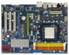
ASRock K10N7SLI Quick Installation Guide - Page 28
eSA, 8 eSATAII Inter, AII Inter, AII Interface Introduction, face Introduction, English
 |
View all ASRock K10N7SLI manuals
Add to My Manuals
Save this manual to your list of manuals |
Page 28 highlights
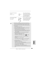
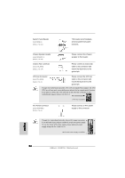
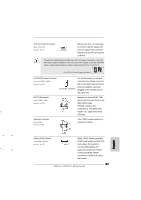
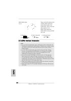
HDMI_SPDIF Cable (Optional) A. black end C B A Please connect the black end (A) of HDMI_SPDIF cable to the HDMI_SPDIF header on the motherboard. Then connect the white end (B or C) of HDMI_SPDIF cable to the HDMI_SPDIF connector of HDMI VGA card. B. white end (2-pin) C. white end (3-pin) 2.8 eSATAII Interface Introduction NOTE: 1. If you set "SATA Operation Mode" option in BIOS setup to AHCI or RAID mode, Hot Plug function is supported with eSATAII devices. Therefore, you can insert or remove your eSATAII devices to the eSATAII ports while the system is power-on and in working condition. 2. If you set "SATA Operation Mode" option in BIOS setup to IDE mode, Hot Plug function is not supported with eSATAII devices. If you still want to use eSATAII function in IDE mode, please insert or remove your eSATAII devices to the eSATAII ports only when the system is power-off. 3. If you want to use the eSATAII HDD as an OS disk, please set "SATA Operation Mode" option in BIOS setup to IDE mode. If you want to use the eSATAII HDD as a removable data disk, please set "SATA Operation Mode" option in BIOS setup to RAID mode. If you want to add the eSATAII HDD as a RAID disk, please set "SATA Operation Mode" option in BIOS setup to RAID mode. 4. Please do not configure your eSATAII HDD as a RAID disk; otherwise, it may affect the Hot Plug function that eSATAII HDD should have. 5. Please refer to page 30 to 31 for detailed information of RAID mode, IDE mode and AHCI mode. English 28 ASRock K10N7SLI Motherboard
-
 1
1 -
2
-
3
-
4
-
5
-
6
-
7
-
8
-
9
-
10
-
11
-
12
-
13
-
14
-
15
-
16
-
17
-
18
-
19
-
20
-
21
-
22
-
 23
23 -
 24
24 -
 25
25 -
 26
26 -
 27
27 -
 28
28 -
 29
29 -
 30
30 -
 31
31 -
 32
32 -
 33
33 -
34
-
35
-
36
-
37
-
38
-
39
-
40
-
41
-
42
-
43
-
44
-
45
-
46
-
47
-
48
-
49
-
50
-
51
-
52
-
53
-
54
-
55
-
56
-
57
-
58
-
59
-
60
-
61
-
62
-
63
-
64
-
65
-
66
-
67
-
68
-
69
-
70
-
71
-
72
-
73
-
74
-
75
-
76
-
77
-
78
-
79
-
80
-
81
-
82
-
83
-
84
-
85
-
86
-
87
-
88
-
89
-
90
-
91
-
92
-
93
-
94
-
95
-
96
-
97
-
98
-
99
-
100
-
101
-
102
-
103
-
104
-
105
-
106
-
107
-
108
-
109
-
110
-
111
-
112
-
113
-
114
-
115
-
116
-
117
-
118
-
119
-
120
-
121
-
122
-
123
-
124
-
125
-
126
-
127
-
128
-
129
-
130
-
131
-
132
-
133
-
134
-
135
-
136
-
137
-
138
-
139
-
140
-
141
-
142
-
143
-
144
-
145
-
146
-
147
-
148
-
149
-
150
-
151
-
152
-
153
-
154
-
155
-
156
-
157
-
158
-
159
-
160
-
161
-
162
-
163
-
164
-
165
-
166
-
167
-
168
-
169
-
170
-
171
-
172
-
173
-
174
-
175
-
176
-
177
-
178
-
179
-
180
-
181
-
182
-
183
-
184
-
185
-
186
-
187
-
188
-
189
-
190
-
191
-
192
-
193
-
194
-
195
-
196
 |
 |
