ASRock K7VM3 User Manual - Page 12
Expansion Slots PCI, AMR, and AGP Slots, Installing an expansion card
 |
View all ASRock K7VM3 manuals
Add to My Manuals
Save this manual to your list of manuals |
Page 12 highlights
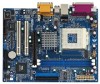
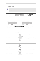
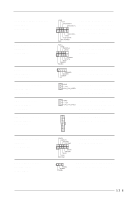
2.6 Expansion Slots (PCI, AMR, and AGP Slots) There are 2 PCI slots, 1 AMR slot, and 1 AGP slot on K7VM3 motherboard. PCI slots: PCI slots are used to install expansion cards that have the 32-bit PCI interface. AMR slot: AMR slot is used to insert an AMR modem card with v.92 Modem functionality. AGP slot: The AGP slot is used to install a graphics card. The ASRock AGP slot has a special locking mechanism which can securely fasten the graphics card inserted. Installing an expansion card Step 1. Before installing the expansion card, read the documentation of the expansion card and make necessary hardware settings for the card. Step 2. Remove the system unit cover (if your motherboard is already installed in a chassis). Step 3. Remove the bracket facing the slot that you intend to use. Keep the screws for later use. Step 4. Align the card connector with the slot and press firmly until the card is completely seated on the slot. Step 5. Fasten the card to the chassis with screws. Step 6. Replace the system cover. 12
-
 1
1 -
2
-
3
-
4
-
5
-
6
-
 7
7 -
 8
8 -
 9
9 -
 10
10 -
 11
11 -
 12
12 -
 13
13 -
 14
14 -
 15
15 -
 16
16 -
 17
17 -
18
-
19
-
20
-
21
-
22
-
23
-
24
-
25
-
26
-
27
-
28
-
29
-
30
 |
 |
