ASRock K7VT4-4X User Manual - Page 17
pin CHA_FAN1
 |
View all ASRock K7VT4-4X manuals
Add to My Manuals
Save this manual to your list of manuals |
Page 17 highlights
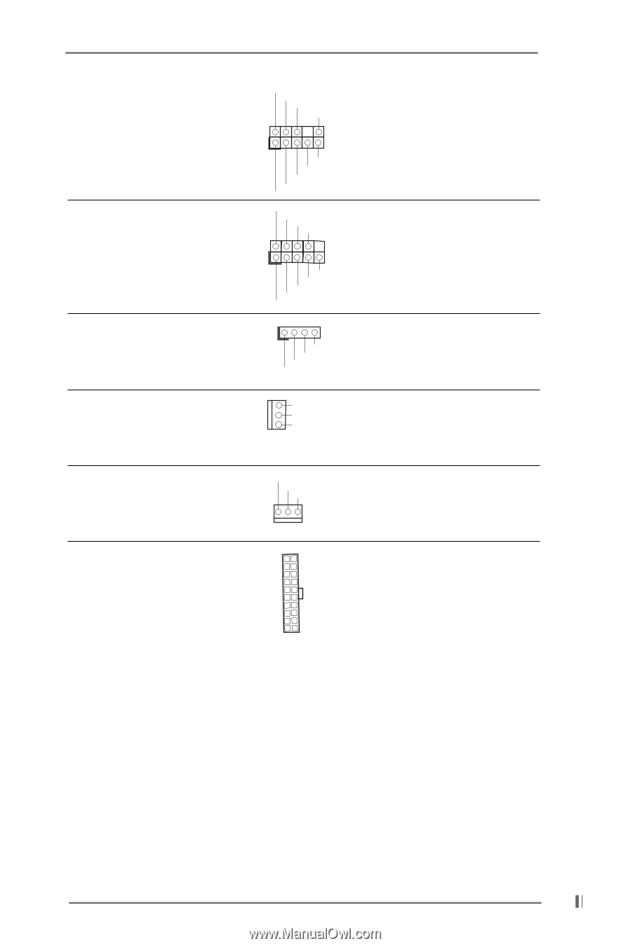
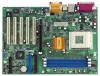
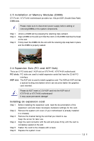
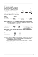
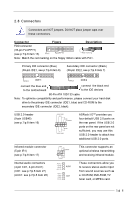
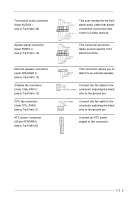
Front panel audio connector (9-pin AUDIO1) (see p.7/p.8 item 24) System panel connector (9-pin PANEL1) (see p.7/p.8 item 14) External speaker connector (4-pin SPEAKER 1) (see p.7/p.8 item 15) Chassis fan connector (3-pin CHA_FAN1) (see p.7/p.8 item 12) CPU fan connector (3-pin CPU_FAN1) (see p.7/p.8 item 2) ATX power connector (20-pin ATXPWR1) (see p.7/p.8 item 6) GND +5VA BACKOUT-R BACKOUT-L 1 A U D - O U T- L DUMMY A U D - O U T- R MIC-POWER MIC PLED+ PLEDPWRBTN# GND 1 DUMMY RESET# GND HDLEDHDLED+ This is an interface for the front panel audio cable that allows convenient connection and control of audio devices. This connector accommodates several system front panel functions. 1 SPEAKER DUMMY DUMMY +5V This connector allows you to attach to an external speaker. GND +12V CHA_FAN_SPEED Connect the fan cable to the connector matching the black wire to the ground pin. CPU_FAN_SPEED +12V GND Connect the fan cable to the connector matching the black wire to the ground pin. Connect an ATX power supply to the connector. 17
-
 1
1 -
2
-
3
-
4
-
5
-
6
-
7
-
8
-
9
-
10
-
11
-
 12
12 -
 13
13 -
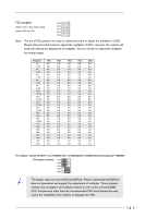 14
14 -
 15
15 -
 16
16 -
 17
17 -
 18
18 -
 19
19 -
 20
20 -
 21
21 -
 22
22 -
23
-
24
-
25
-
26
-
27
-
28
-
29
-
30
 |
 |