ASRock K7VT6-C User Manual - Page 16
Front Panel Audio Connector
 |
View all ASRock K7VT6-C manuals
Add to My Manuals
Save this manual to your list of manuals |
Page 16 highlights
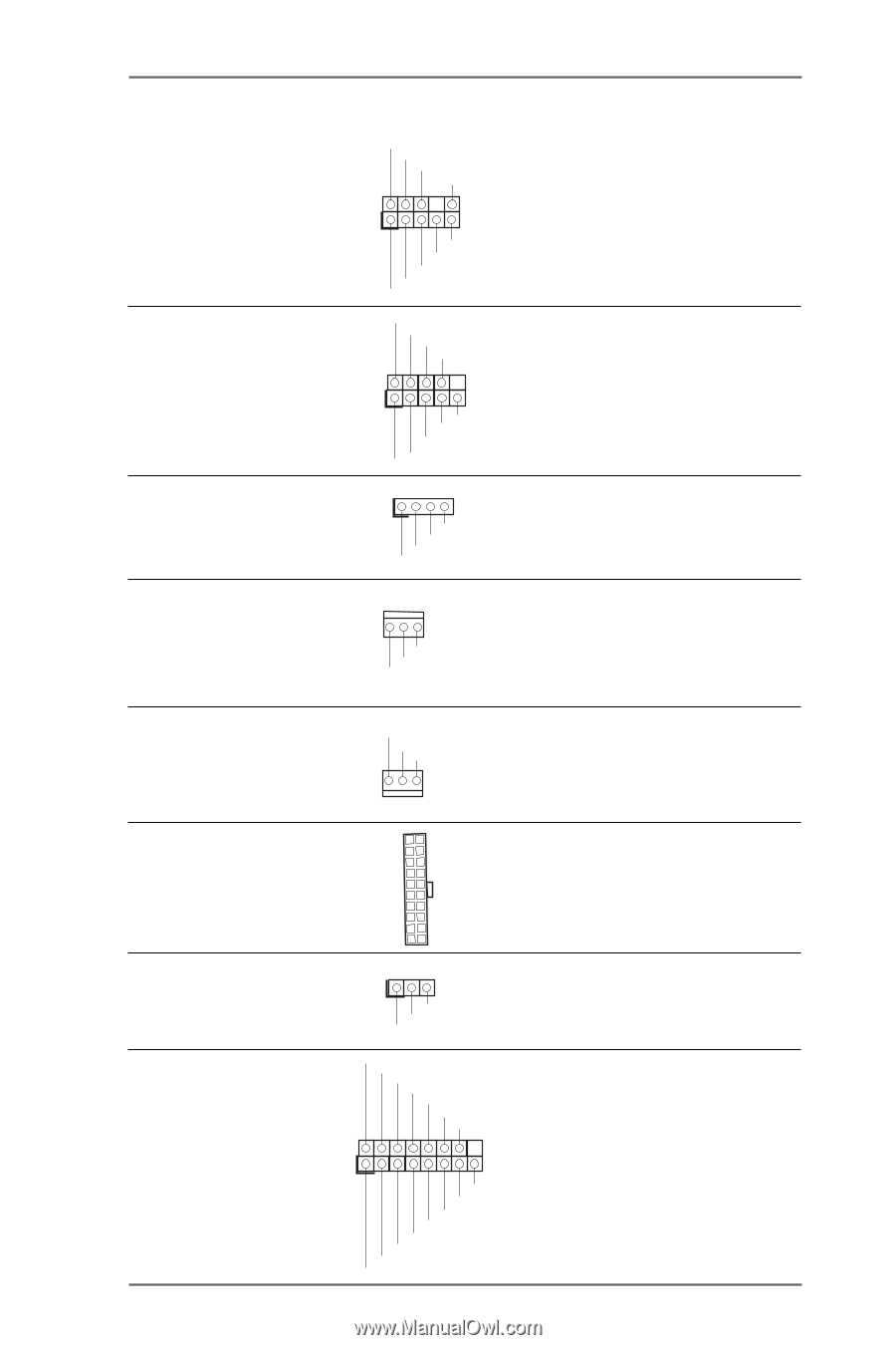
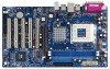
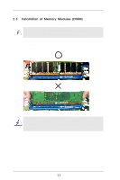
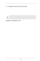
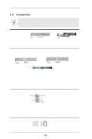
Front Panel Audio Connector (9-pin AUDIO1) (see p.7 item 21) GND +5VA BACKOUT-R BACKOUT-L 1 A U D - O U T- L GND A U D - O U T- R MIC-POWER MIC System Panel Connector (9-pin PANEL1) (see p.7 item 14) Chassis Speaker Connector (4-pin SPEAKER 1) (see p.7 item 15) PLED+ PLEDPWRBTN# GND 1 GND RESET# GND HDLEDHDLED+ 1 SPEAKER DUMMY DUMMY +5V Chassis Fan Connector (3-pin CHA_FAN1) (see p.7 item 13) GND +12V CHA_FAN_SPEED This is an interface for front panel audio cable that allows convenient connection and control of audio devices. This connector accommodates several system front panel functions. Please connect the chassis speaker to this connector. Please connect a chassis fan cable to this connector and match the black wire to the ground pin. CPU Fan Connector (3-pin CPU_FAN1) (see p.7 item 2) CPU_FAN_SPEED +12V GND Please connect a CPU fan cable to this connector and match the black wire to the ground pin. ATX Power Connector (20-pin ATXPWR1) (see p.7 item 6) Please connect an ATX power supply to this connector. Power LED Connector (3-pin PWR_LED1) (see p.7 item 12) Game Connector (15-pin GAME1) (see p.7 item 23) 1 PLED- PLED+ PLED+ +5V JBB1 JBX MIDI_OUT J2Y JBY MIDI_IN 1 +5V JAB2 JAY GND GND JAX JAB1 +5V 16 Please connect a 3-pin power LED cable to this connector. Connect a Game cable to this connector if the Game port bracket is installed.
-
 1
1 -
2
-
3
-
4
-
5
-
6
-
7
-
8
-
9
-
10
-
 11
11 -
 12
12 -
 13
13 -
 14
14 -
 15
15 -
 16
16 -
 17
17 -
 18
18 -
 19
19 -
 20
20 -
 21
21 -
22
-
23
-
24
-
25
-
26
-
27
-
28
-
29
-
30
 |
 |