ASRock M266A R3.0 User Manual - Page 7
P4M266A, Chipset
 |
View all ASRock M266A R3.0 manuals
Add to My Manuals
Save this manual to your list of manuals |
Page 7 highlights
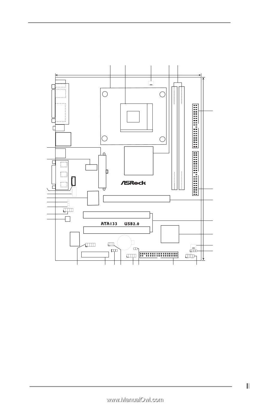
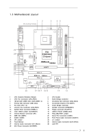
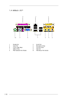
1.3 Motherboard Layout 12 19.1cm (7.5 in) 3 45 PS/2 Mouse PS/2 Keyboard VGA CPU_FAN1 IDE2 6 PARALLEL PORT DDR DIMM1 (64/72 bit, 184-pin module) DDR DIMM2 (64/72 bit, 184-pin module) 24.4cm (9.6 in) mPGA478B 29 28 27 26 25 24 23 22 21 GGAAMMEE AAUUDDIIOO11 ATXPWR1 LAN (optional) USB 2.0 Ports USB 2.0 Ports Line out LAN PHY LiLInnineein CD1 MMIniicc in AUX1 JL1 JR1 2MB BIOS 1 AUDIO1 AUDIO CODEC VIA P4M266A Chipset M266A AGP1 PCI 1 IDE1 Super I/O PCI 2 COM1 IR1 1 1 PS2_USB_PWR1 1 AMR1 CMOS Battery CLRCMOS1 FLOPPY1 USB45 1 20 19 1817 1615 VIA VT8235 CHA_FAN1 SPEAKER11 PLED PWRBTN PANEL1 1 HDLED RST 14 13 7 8 9 10 11 12 1 CPU Heatsink Retention Module 3 CPU Fan Connector (CPU_FAN1) 5 184-pin DDR DIMM Slots (DDR DIMM1- 2) 7 Primary IDE Connector (IDE1, Blue) 9 PCI Slots (PCI 1- 2) 11 Chassis Fan Connector (CHA_FAN1) 13 System Panel Connector (PANEL1) 15 Clear CMOS Jumper (CLRCMOS1) 17 Infrared Module Connector (IR1) 19 AMR Slot (AMR1) 21 AUDIO CODEC 23 JR1 Jumper 25 Flash Memory 27 Internal Audio Connector: CD1 (Black) 29 ATX Power Connector (ATXPWR1) 2 CPU Socket 4 North Bridge Controller 6 Secondary IDE Connector (IDE2, Black) 8 Accelerated Graphics Port (AGP1) 10 South Bridge Controller 12 Speaker Connector (SPEAKER 1) 14 Floppy Connector (FLOPPY1) 16 USB 2.0 Header (USB45, Blue) 18 PS2_USB_PWR1 Jumper 20 Serial Port Connector (COM1) 22 Front Panel Audio Connector (AUDIO1) 24 JL1 Jumper 26 Internal Audio Connector: AUX1 (White) 28 LAN PHY 7
-
 1
1 -
 2
2 -
 3
3 -
 4
4 -
 5
5 -
 6
6 -
 7
7 -
 8
8 -
 9
9 -
 10
10 -
 11
11 -
 12
12 -
13
-
14
-
15
-
16
-
17
-
18
-
19
-
20
-
21
-
22
-
23
-
24
-
25
-
26
-
27
 |
 |