ASRock M3A-GLAN User Manual - Page 20
Chassis and Power Fan Connectors
 |
View all ASRock M3A-GLAN manuals
Add to My Manuals
Save this manual to your list of manuals |
Page 20 highlights
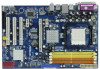
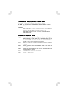
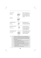
For Windows® XP / XP 64-bit OS: Click "Audio I/O", select "Connector Settings" , choose "Disable front panel jack detection", and save the change by clicking "OK". For Windows® VistaTM / VistaTM 64-bit OS: Click the right-top "Folder" icon , choose "Disable front panel jack detection", and save the change by clicking "OK". G. To activate the front mic. For Windows® XP / XP 64-bit OS: Please select "Front Mic" as default record device. If you want to hear your voice through front mic, please deselect "Mute" icon in "Front Mic" of "Playback" portion. For Windows® VistaTM / VistaTM 64-bit OS: Go to the "Front Mic" Tab in the Realtek Control panel. Click "Set Default Device" to make the Front Mic as the default record device. System Panel Header (9-pin PANEL1) (see p.10 No. 17) PLED+ PLEDPWRBTN# GND 1 DUMMY RESET# GND HDLEDHDLED+ Chassis Speaker Header (4-pin SPEAKER 1) (see p.10 No. 19) 1 SPEAKER DUMMY DUMMY +5V Chassis and Power Fan Connectors (3-pin CHA_FAN1) (see p.10 No. 20) GND +12V CHA_FAN_SPEED (3-pin PWR_FAN1) (see p.10 No. 28) PWR_FAN_SPEED +12V GND This header accommodates several system front panel functions. Please connect the chassis speaker to this header. Please connect the fan cables to the fan connectors and match the black wire to the ground pin. CPU Fan Connector (4-pin CPU_FAN1) (see p.10 No. 31) FAN_SPEED_CONTROL 4 CPU_FAN_SPEED 3 +12V 2 GND 1 Please connect the CPU fan cable to this connector and match the black wire to the ground pin. 20
-
 1
1 -
2
-
3
-
4
-
5
-
6
-
7
-
8
-
9
-
10
-
11
-
12
-
13
-
14
-
 15
15 -
 16
16 -
 17
17 -
 18
18 -
 19
19 -
 20
20 -
 21
21 -
 22
22 -
 23
23 -
 24
24 -
 25
25 -
26
-
27
-
28
-
29
-
30
-
31
-
32
-
33
-
34
-
35
-
36
-
37
-
38
-
39
-
40
-
41
-
42
-
43
-
44
-
45
-
46
-
47
-
48
-
49
-
50
-
51
-
52
-
53
 |
 |