ASRock N68C-GS FX Quick Installation Guide - Page 2
Motherboard Layout, GS FX / N68C - can i have memory in all 4 slots
 |
View all ASRock N68C-GS FX manuals
Add to My Manuals
Save this manual to your list of manuals |
Page 2 highlights
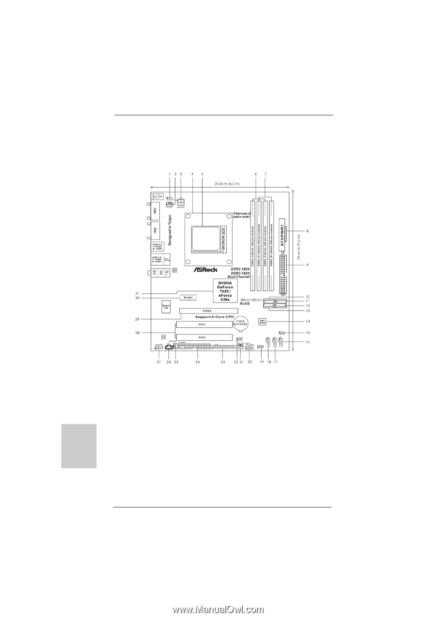
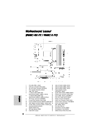
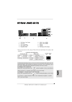
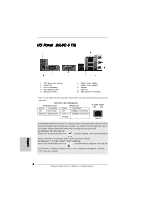
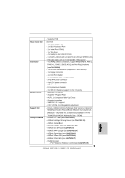
Motherboard Layout (N68C-GS FX / N68C-S FX) English 1 PS2_USB_PWR1 Jumper 16 USB 2.0 Header (USB8_9, Blue) 2 CPU Fan Connector (CPU_FAN1) 17 USB 2.0 Header (USB6_7, Blue) 3 ATX 12V Power Connector (ATX12V1) 18 USB 2.0 Header (USB4_5, Blue) 4 CPU Heatsink Retention Module 19 Chassis Speaker Header 5 AMD CPU Socket (SPEAKER 1, White) 6 2 x 240-pin DDR2 DIMM Slots 20 System Panel Header (PANEL1, White) (Dual Channel: DDRII_1, DDRII_2; Yellow) 21 Chassis Fan Connector (CHA_FAN1) 7 2 x 240-pin DDR3 DIMM Slots 22 Clear CMOS Jumper (CLRCMOS1) (Dual Channel: DDR3_A1, DDR3_B1; Blue) 23 Print Port Header (LPT1, Purple) 8 ATX Power Connector (ATXPWR1) 24 Floppy Connector (FLOPPY1) 9 Primary IDE Connector (IDE1, Blue) 25 Power Fan Connector (PWR_FAN1) 10 Primary SATAII Connector (SATAII_1 (PORT 0.0)) 26 Internal Audio Connector: CD1 (White) 11 Third SATAII Connector (SATAII_3 (PORT 1.0)) 27 Front Panel Audio Header 12 Fourth SATAII Connector (SATAII_4 (PORT 1.1)) (HD_AUDIO1, White) 13 Secondary SATAII Connector 28 PCI Slots (PCI1- 2) (SATAII_2 (PORT 0.1)) 29 PCI Express x16 Slot (PCIE2) 14 SPI Flash Memory (8Mb) 30 PCI Express x1 Slot (PCIE1) 15 USB_PWR2 Jumper 31 NVIDIA GeForce 7025 / nForce 630a 2 ASRock N68C-GS FX / N68C-S FX Motherboard
-
 1
1 -
 2
2 -
 3
3 -
 4
4 -
 5
5 -
 6
6 -
 7
7 -
 8
8 -
9
-
10
-
11
-
12
-
13
-
14
-
15
-
16
-
17
-
18
-
19
-
20
-
21
-
22
-
23
-
24
-
25
-
26
-
27
-
28
-
29
-
30
-
31
-
32
-
33
-
34
-
35
-
36
-
37
-
38
-
39
-
40
-
41
-
42
-
43
-
44
-
45
-
46
-
47
-
48
-
49
-
50
-
51
-
52
-
53
-
54
-
55
-
56
-
57
-
58
-
59
-
60
-
61
-
62
-
63
-
64
-
65
-
66
-
67
-
68
-
69
-
70
-
71
-
72
-
73
-
74
-
75
-
76
-
77
-
78
-
79
-
80
-
81
-
82
-
83
-
84
-
85
-
86
-
87
-
88
-
89
-
90
-
91
-
92
-
93
-
94
-
95
-
96
-
97
-
98
-
99
-
100
-
101
-
102
-
103
-
104
-
105
-
106
-
107
-
108
-
109
-
110
-
111
-
112
-
113
-
114
-
115
-
116
-
117
-
118
-
119
-
120
-
121
-
122
-
123
-
124
-
125
-
126
-
127
-
128
-
129
-
130
-
131
-
132
-
133
-
134
-
135
-
136
-
137
-
138
-
139
-
140
-
141
-
142
-
143
-
144
-
145
-
146
-
147
-
148
-
149
-
150
-
151
-
152
-
153
-
154
-
155
-
156
-
157
-
158
-
159
-
160
-
161
-
162
-
163
-
164
-
165
-
166
-
167
-
168
-
169
-
170
-
171
-
172
-
173
-
174
-
175
-
176
 |
 |