ASRock P43R1600Twins-WiFi User Manual - Page 26
This header supports WiFi+AP - wifi 802 11n
 |
View all ASRock P43R1600Twins-WiFi manuals
Add to My Manuals
Save this manual to your list of manuals |
Page 26 highlights
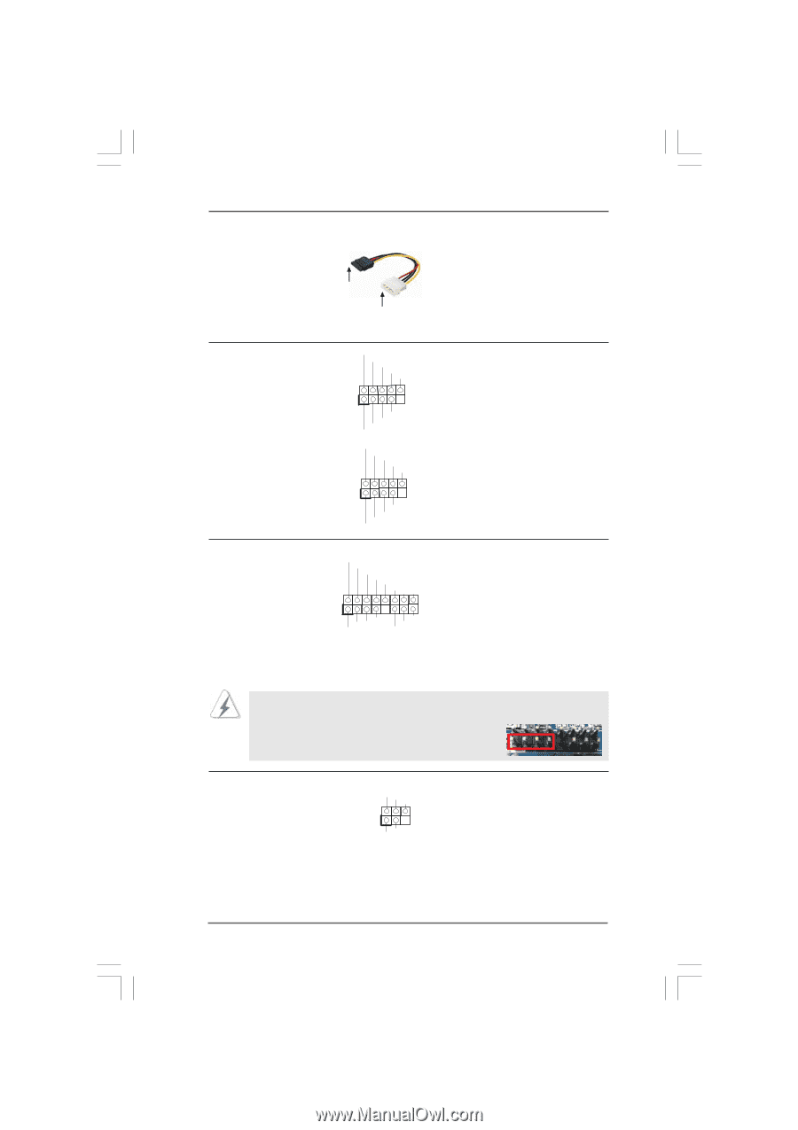
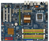
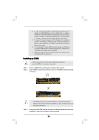
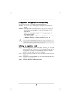
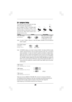
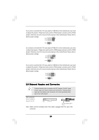
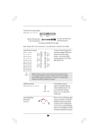
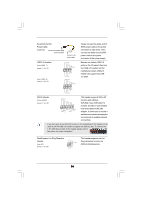
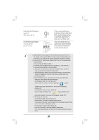
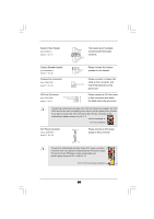
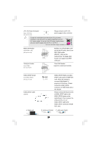
Serial ATA (SATA) Power Cable (Optional) connect to the SATA HDD power connector connect to the power supply USB 2.0 Headers (9-pin USB6_7) (see p.11 No. 19) (9-pin USB4_5) (see p.11 No. 18) USB_PWR P-7 P+7 GND DUMMY 1 GND P+6 P-6 USB_PWR USB_PWR P-5 P+5 GND DUMMY 1 GND P+4 P-4 USB_PWR Please connect the black end of SATA power cable to the power connector on each drive. Then connect the white end of SATA power cable to the power connector of the power supply. Besides six default USB 2.0 ports on the I/O panel, there are two USB 2.0 headers on this motherboard. Each USB 2.0 header can support two USB 2.0 ports. WiFi/E Header (15-pin WIFI/E) (see p.11 No. 32) USB+5V_2 TXN TXP GND2 PCIE_RST# +3 SVB RXN R XP 1 GND1 D0-D0+ PexCLK PexCLK# USB+5V_1 PME# This header supports WiFi+AP function with ASRock WiFi-802.11g or WiFi-802.11n module, an easy-to-use wireless local area network (WLAN) adapter. It allows you to create a wireless environment and enjoy the convenience of wireless network connectivity. If you don't plan to use WiFi+AP functin on this motherboard, this header can be used as a 4-Pin USB 2.0 header to support one USB 2.0 port. To connect the 4-Pin USB device cable to this header, please refer to this picture for proper installation. DeskExpress Hot Plug Detection Header (5-pin IR1) (see p.11 No. 26) IRTX +5VSB Hotplug# 1 GND IRRX This header supports the Hot Plug detection function for ASRock DeskExpress. 26
-
 1
1 -
2
-
3
-
4
-
5
-
6
-
7
-
8
-
9
-
10
-
11
-
12
-
13
-
14
-
15
-
16
-
17
-
18
-
19
-
20
-
 21
21 -
 22
22 -
 23
23 -
 24
24 -
 25
25 -
 26
26 -
 27
27 -
 28
28 -
 29
29 -
 30
30 -
 31
31 -
32
-
33
-
34
-
35
-
36
-
37
-
38
-
39
-
40
-
41
-
42
-
43
-
44
-
45
-
46
-
47
-
48
-
49
-
50
-
51
-
52
-
53
-
54
-
55
-
56
-
57
-
58
-
59
-
60
-
61
-
62
-
63
-
64
-
65
-
66
-
67
-
68
 |
 |