ASRock P45XE-R User Manual - Page 37
and one of the orange eSATAII connector eSATAII_BOTTOM Port 5; see p.11
 |
View all ASRock P45XE-R manuals
Add to My Manuals
Save this manual to your list of manuals |
Page 37 highlights
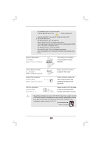
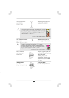
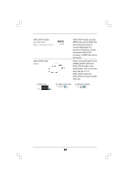
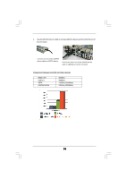
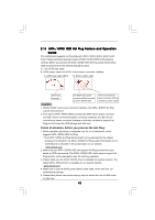
1. If you just plan to install one eSATAII device to this motherboard, it is recommended to enable the bottom eSATAII port of the I/O shield. In order to enable the bottom eSATAII port of the I/O shield, you need to connect one of the orage SATAII connectors (SATAII_6 (Port 5); see p.11 No.19 or p.12 No.18) and one of the orange eSATAII connectors (eSATAII_BOTTOM (Port 5); see p.11/12 No.1) with a SATA data cable first. Then the bottom eSATAII port of the I/O shield is enabled. Connect the SATA data cable to one of the orange SATAII connector (SATAII_6 (Port 5)) Connect the SATA data cable to one of the orange eSATAII connector (eSATAII_BOTTOM (Port 5)) 2. If you plan to install two eSATAII devices to this motherboard, you need to enable both the top and the bottom eSATAII ports of the I/O shield. In order to enable the top and the bottom eSATAII ports of the I/O shield, you have to connect one of the orange SATAII connector (SATAII_6 (Port 5); see p.11 No.19 or p.12 No.18) and one of the orange eSATAII connector (eSATAII_BOTTOM (Port 5); see p.11/ 12 No.1) with a SATA data cable first, and then connect the other orange SATAII connector (SATAII_5 (Port 4); see p.11 No.21 or p.12 No.20) and the other orange eSATAII connector (eSATAII_TOP (Port 4); see p.11 No.39 or p.12 No.38) with the other SATA data cable. After that, both the top and the bottom eSATAII ports of the I/O shield are enabled. Connect the SATA data Connect the SATA cables to both orange data cables to both SATAII connectors orange eSATAII (SATAII_6 (Port 5) and connectors (eSATAII_ SATAII_5 (Port 4)) BOTTOM (Port 5) and eSATAII_TOP (Port 4)) 37
-
 1
1 -
2
-
3
-
4
-
5
-
6
-
7
-
8
-
9
-
10
-
11
-
12
-
13
-
14
-
15
-
16
-
17
-
18
-
19
-
20
-
21
-
22
-
23
-
24
-
25
-
26
-
27
-
28
-
29
-
30
-
31
-
 32
32 -
 33
33 -
 34
34 -
 35
35 -
 36
36 -
 37
37 -
 38
38 -
 39
39 -
 40
40 -
 41
41 -
 42
42 -
43
-
44
-
45
-
46
-
47
-
48
-
49
-
50
-
51
-
52
-
53
-
54
-
55
-
56
-
57
-
58
-
59
-
60
-
61
-
62
-
63
-
64
-
65
-
66
-
67
-
68
-
69
-
70
-
71
-
72
-
73
-
74
-
75
-
76
-
77
-
78
 |
 |