ASRock P4Dual-915GL User Manual
ASRock P4Dual-915GL Manual
 |
View all ASRock P4Dual-915GL manuals
Add to My Manuals
Save this manual to your list of manuals |
ASRock P4Dual-915GL manual content summary:
- ASRock P4Dual-915GL | User Manual - Page 1
P4Dual-915GL User Manual Version 1.2 Published June 2005 Copyright©2005 ASRock INC. All rights reserved. 1 - ASRock P4Dual-915GL | User Manual - Page 2
for backup purpose, without written consent of ASRock Inc. Products and corporate names appearing in this manual may or may not be registered trademarks or in this manual. With respect to the contents of this manual, ASRock does not provide warranty of any kind, either expressed or implied, - ASRock P4Dual-915GL | User Manual - Page 3
Cards Lists for AGI Slot 8 1.4 Supported PCI Express VGA Cards Lists for AGI Express Slot (PCI Express x 4 10 1.5 Motherboard Layout 11 1.6 ASRock 8CH I/O 12 2 Installation 13 Pre-installation Precautions 13 2.1 CPU Installation 14 2.2 Installation of CPU Fan and Heatsink 14 2.3 Installation - ASRock P4Dual-915GL | User Manual - Page 4
4 Software Support 37 4.1 Install Operating System 37 4.2 Support CD Information 37 4.2.1 Running Support CD 37 4.2.2 Drivers Menu 37 4.2.3 Utilities Menu 37 4.2.4 Contact Information 37 4 - ASRock P4Dual-915GL | User Manual - Page 5
of this manual occur, the updated version will be available on ASRock website without further notice. You may find the latest memory and CPU support lists on ASRock website as well. ASRock website http://www.asrock.com 1.1 Package Contents ASRock P4Dual-915GL Motherboard (Micro ATX Form Factor - ASRock P4Dual-915GL | User Manual - Page 6
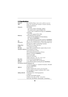
Platform: Micro ATX Form Factor: 9.6-in x 8.6-in, 24.4 cm x 21.8 cm CPU: Socket 478, supports Intel® Pentium® 4 / Celeron® (Prescott, Northwood) processor Chipsets: North Bridge: Intel® 915GL chipset, FSB @ 800 / 533MHz, (This chipset doesn't support FSB400 CPU) supports Hyper-Threading - ASRock P4Dual-915GL | User Manual - Page 7
of PCI Express VGA card, please refer to the installation guide on page 16. 7. Power Management for USB 2.0 works fine under Microsoft® Windows® XP SP1 / 2000 SP4. 8. For microphone input, this motherboard supports both stereo and mono modes. For audio output, this motherboard supports - ASRock P4Dual-915GL | User Manual - Page 8
(for Windows 2000/Windows XP) I. AGP 4X Graphics Chip Vendor n-VIDIA ATI Model Name ASUS AGP-V8170 ASUS AGP-V9180 Magic INNO3D GeForce4 MX440SE Insignia GeForce MX440SE LEADTEK A170TH GIGABYTE GV-AP64S-H POWERCOLOR RADEON 9100 Transcend TS64MVDR7 For the latest updates of the supported AGP VGA - ASRock P4Dual-915GL | User Manual - Page 9
. AGP 8X Graphics Chip Vendor n-VIDIA ATI Model Name ASUS AGP-V9570/TD ASUS AGP-V9480 ASUS AGP- RADEON 9250/128M For the latest updates of the supported AGP VGA card list for AGI slot, please visit ASRock website for details. ASRock website: http://www.asrock.com/support/index.htm Note. ATi 9600, - ASRock P4Dual-915GL | User Manual - Page 10
1.4 Supported PCI Express VGA Card List for AGI Express Slot (PCI Express x 4) (for Windows 2000/Windows XP) Graphics Chip Model Name Remark Vendor (VGA BIOS Version) n-VIDIA ASUS Extreme N5900 ASUS EN6600 ASUS EN6800 ASUS Extreme N5750/A ALBATRON GeFORCE 6200TC GIGABYTE GV-NX66128D - ASRock P4Dual-915GL | User Manual - Page 11
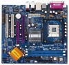
Prescott 800 31 30 29 28 27 26 25 24 23 Top: LINE IN Center: FRONT Bottom: MIC IN CHA_FAN1 COM1 1 P4Dual-915GL USB 2.0 T: USB2 B: USB3 USB 2.0 T: USB0 B: USB1 Top: RJ-45 Top: REAR SPK Center: SIDE SPK Bottom: CTR BASS CD1 ATXPWR1 7.1CH ` Intel 915GL Chipset PCI EXPRESS AGI_EXPRESS1 - ASRock P4Dual-915GL | User Manual - Page 12
1.6 ASRock 8CH I/O 1 Parallel Port 2 RJ-45 Port 3 Side Speaker (Gray) 4 Rear Speaker ( the table below for connection details in accordance with the type of speaker you use. TABLE for Audio Output Connection Audio Output Channels Front Speaker Rear Speaker Central / Bass (No. 7) (No. 4) (No. - ASRock P4Dual-915GL | User Manual - Page 13
Chapter 2 Installation P4Dual-915GL is a Micro ATX form factor (9.6-in x 8.6-in, 24.4 cm x 21.8 cm) motherboard. Before you install the motherboard, study the configuration of your chassis to ensure that the motherboard fits into it. Pre-installation Precautions Take note of the following - ASRock P4Dual-915GL | User Manual - Page 14
Socket Lever Up to 90° CPU Marked Corner Socket Marked Corner STEP 2/STEP 3: Match The CPU Marked Corner to The Socket Marked Corner STEP 4: Push Down And Lock The Socket Lever 2.2 Installation of CPU Fan and Heatsink This motherboard adopts 478-pin CPU socket to support Intel® Pentium®4 CPU - ASRock P4Dual-915GL | User Manual - Page 15
2.3 Installation of Memory Modules (DIMM) P4Dual-915GL motherboard provides two 184-pin DDR (Double Data Rate) DIMM slots, and supports Dual Channel Memory Technology. For dual channel configuration, you always need to install two identical (the same brand, speed, size and chip-type) memory modules - ASRock P4Dual-915GL | User Manual - Page 16
the add-on AGP VGA card or PCI Express VGA card, BIOS setup will automatically disable the onboard VGA. 2. Please make sure to set the BIOS onboard VGA selection into "En abled" if you want this motherboard to support Surround Display. Then the onboard VGA in Windows will be the primary VGA card - ASRock P4Dual-915GL | User Manual - Page 17
PCI Express VGA card, you can easily enjoy the benefits of Surround Display feature. Please make sure to set the BIOS onboard VGA selection into "Enabled", and start your computer with onboard VGA if you want this motherboard to support multi-monitors. For the detailed instruction audio connectors - ASRock P4Dual-915GL | User Manual - Page 18
-pin IDE1, see p.11 No. 10) PIN1 IDE1 connect the blue end connect the black end to the motherboard to the IDE devices 80-conductor ATA 66/100 cable Note: Please refer to the instruction of your IDE device vendor for the details. Serial ATA Connectors (SATA1: see p.11 No. 18) (SATA2 - ASRock P4Dual-915GL | User Manual - Page 19
USB_PWR P-6 P+6 GND DUMMY 1 GND P+7 P-7 USB_PWR ASRock 8CH I/O accommodates 4 default USB 2.0 ports. If those support 2 additional USB 2.0 ports. This header supports an optional wireless transmitting and receiving infrared module. These connectors allow you to receive stereo audio input from sound - ASRock P4Dual-915GL | User Manual - Page 20
(see p.11 No. 11) CPU Fan Connector (3-pin CPU_FAN1) (see p.11 No. 5) ATX Power Connector (20-pin ATXPWR1) ATX 12V Connector (4-pin ATX12V1) (see p.11 No. 2) RRXD1 DDTR#1 DDSR#1 CCTS#1 1 RRI#1 RRTS#1 GND TTXD1 DDCD#1 This COM port header is used to support a COM port module. Please connect an ATX - ASRock P4Dual-915GL | User Manual - Page 21
2.8 Serial ATA (SATA) Hard Disks Installation This motherboard adopts Intel ICH6 south bridge chipset that supports Serial ATA (SATA) hard disks. You may install SATA hard disks on this motherboard for internal storage devices. This section will guide you to install the SATA hard disks. STEP 1: - ASRock P4Dual-915GL | User Manual - Page 22
BIOS FWH chip on the motherboard stores the BIOS SETUP UTILITY. You may run the BIOS SETUP UTILITY when you start up the computer. Please press during the Power-On-Self-Test (POST) to enter the BIOS on. Because the BIOS software is constantly being updated, the following BIOS setup screens and - ASRock P4Dual-915GL | User Manual - Page 23
Exit System Overview System Time System Date [14:00:09] [Wed 01/05/2005] BIOS Version : P4Dual-915GL BIOS P1.00 Processor Type : Intel (R) Pentium (R) 4 CPU 2.40 GHz Processor Speed : 2400 Mhz Microcode Update : F24/1E Cache Size : 512KB Total Memory DIMM 1 DIMM 2 : 512MB with 8MB shared - ASRock P4Dual-915GL | User Manual - Page 24
Defaults Save and Exit Exit v02.54 (C) Copyright 1985-2005, American Megatrends, Inc. CPU Host Frequency While entering setup, BIOS auto detects the present CPU host frequency of this motherboard. The actual CPU host frequency will show in the following item. Boot Failure Guard Enable or disable - ASRock P4Dual-915GL | User Manual - Page 25
for this technology, such as Microsoft® Windows® XP. Set to [Auto] if using Microsoft® Windows® XP, or Linux kernel version 2.4.18 or higher. This option will be hidden if the installed CPU does not support Hyper-Threading technology. Max CPUID Value Limit For Prescott CPU only, some OSes (ex. NT4 - ASRock P4Dual-915GL | User Manual - Page 26
DRAM Frequency If [Auto] is selected, the motherboard will detect the memory module(s) inserted and assigns you select [Auto], the onboard VGA will be automatically disabled when you install AGP 8X or PCI Express X 16 VGA card; the onboard VGA will be enabled without the installation of any add-on - ASRock P4Dual-915GL | User Manual - Page 27
Disabled] for the onboard AC'97 Audio feature. OnBoard MC'97 Modem Select [Auto] or [Disabled] for the onboard MC'97 Modem feature. 3.3.3 ACPI Configuration BIOS SETUP UTILITY Advanced ACPI Configuration Suspend To RAM Restore on AC/Power Loss Ring-In Power On PCI Devices Power On PS / 2 Keyboard - ASRock P4Dual-915GL | User Manual - Page 28
3.3.4 IDE Configuration BIOS SETUP UTILITY Advanced IDE Configuration ATA/IDE [IDE 1, SATA 2, SATA 4], then SATA1, SATA3 will not work. Because Intel® ICH6 south bridge only supports four IDE devices under legacy OS (Windows NT), you have to choose [SATA 1, SATA 2, SATA 3, SATA 4], [ - ASRock P4Dual-915GL | User Manual - Page 29
as the example in the following instruction. BIOS SETUP UTILITY Advanced Primary IDE Master :ST340014A :40.0 GB :Supported :16Sectors :4 :MultiWord DMA-2 :Ultra DMA-5 :Supported [Auto] [Auto] MB under DOS and Windows; for Netware and UNIX user, select [Disabled] to disable the LBA/Large mode. - ASRock P4Dual-915GL | User Manual - Page 30
], [Auto], [Enabled]. 32-Bit Data Transfer Use this item to enable 32-bit access to maximize the IDE hard disk data transfer rate. 3.3.5 PCIPnP Configuration BIOS SETUP UTILITY Advanced PCI / PnP Configuration WARNING: Setting wrong values in below actions may cause system to malfunction - ASRock P4Dual-915GL | User Manual - Page 31
3.3.6 Floppy Configuration In this section, you may configure the type of your floppy drive. BIOS SETUP UTILITY Advanced Floppy Configuration Floppy A Floppy B [1.44 MB 312"] [Disabled] Select the type of floppy drive connected to the system. +F1 F9 F10 ESC Select Screen Select Item Change - ASRock P4Dual-915GL | User Manual - Page 32
Parallel Port Address Use this item to set the address for the onboard parallel port or disable it. Configuration options: [Disabled], [378], and [278]. Parallel Port Mode Use this item to set the operation mode of the parallel port. The default value is [ECP+EPP]. If this option is set to [ECP+EPP - ASRock P4Dual-915GL | User Manual - Page 33
controller. USB 2.0 Support Use this item to enable or disable the USB 2.0 support. Legacy USB Support Use this item to enable or disable the support to emulate legacy of the CPU temperature, motherboard temperature, CPU fan speed, chassis fan speed, and the critical voltage. BIOS SETUP UTILITY - ASRock P4Dual-915GL | User Manual - Page 34
it will display the available devices on your system for you to configure the boot settings and the boot priority. Main Advanced BIOS SETUP UTILITY H/W Monitor Boot Security Exit Boot Settings Boot Settings Configuration Configure Settings during System Boot. 1st Boot Device 2nd Boot Device - ASRock P4Dual-915GL | User Manual - Page 35
you may set or change the supervisor/user password for the system. For the user password, you may also clear it. BIOS SETUP UTILITY Main Advanced H/W Monitor Boot Security Exit Security Settings Supervisor Password : Not Installed User Password : Not Installed Change Supervisor Password - ASRock P4Dual-915GL | User Manual - Page 36
and exit setup?" Select [OK] to save the changes and exit the BIOS SETUP UTILITY. Discard Changes and Exit When you select this option, it message, "Discard changes and exit setup?" Select [OK] to exit the BIOS SETUP UTILITY without saving any changes. Discard Changes When you select this option - ASRock P4Dual-915GL | User Manual - Page 37
install the necessary drivers to activate the devices. 4.2.3 Utilities Menu The Utilities Menu shows the applications software that the motherboard supports. Click on a specific item then follow the installation wizard to install it. 4.2.4 Contact Information If you need to contact ASRock or want to
-
 1
1 -
 2
2 -
 3
3 -
 4
4 -
 5
5 -
 6
6 -
 7
7 -
8
-
9
-
10
-
11
-
12
-
13
-
14
-
15
-
16
-
17
-
18
-
19
-
20
-
21
-
22
-
23
-
24
-
25
-
26
-
27
-
28
-
29
-
30
-
31
-
32
-
33
-
34
-
35
-
36
-
37
 |
 |

1
P4Dual-915GL
User Manual
Version 1.2
Published June 2005
Copyright©2005 ASRock INC. All rights reserved.