ASRock P4V88 User Manual - Page 8
PT880, Chipset - bios
 |
View all ASRock P4V88 manuals
Add to My Manuals
Save this manual to your list of manuals |
Page 8 highlights
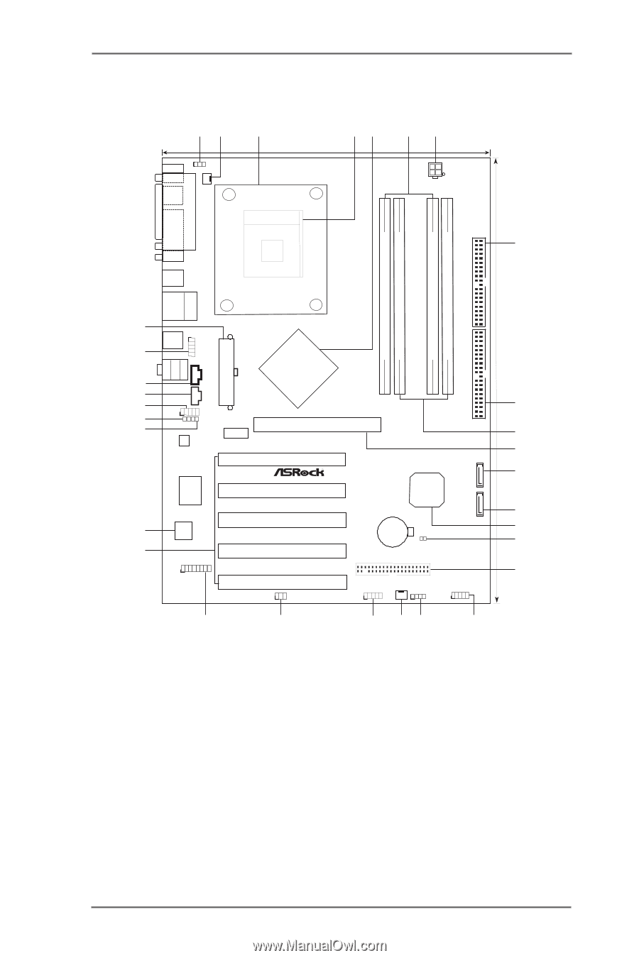
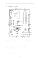
1.3 Motherboard Layout 12 3 45 21.8cm (8.6 in) 67 PS2 Mouse 1 PS2_USB_PWR1 CPU_FAN1 PS2 Keyboard ATX12V1 PARALLEL PORT COM1 PGA478 IDE2 8 DDR1 (64/72 bit, 184-pin module) DDR2 (64/72 bit, 184-pin module) DDR3 (64/72 bit, 184-pin module) DDR4 (64/72 bit, 184-pin module) 30.5cm (12.0 in) 31 30 29 28 27 26 25 24 23 Top: Line In Center: Line Out Bottom: Mic In USB 2.0 T: USB2 B: USB3 USB 2.0 T: USB0 B: USB1 Top: RJ-45 USB 2.0 T: USB4 1 B: USB5 USB4_5 ATXPWR1 CD1 AUX1 1 JR1 AUDIO1 JL1 Audio CODEC LAN PHY VPIACT8h8ip0seAtGP 8X 1.5V_AGP1 PCI 1 IDE1 SATA2 Super I/O 2MB BIOS GAME1 PCI 2 USB2.0 FSB800 DDR400 PCI 3 5.1 CH PCI 4 ATA133 SATA PCI 5 1 IR1 P4V88+ VIA VT8237 CMOS Battery CLRCMOS1 FLOPPY1 SATA1 USB67 1 CHA_FAN1 SPEAKER1 1 PANEL 1 PLED PWRBTN 1 HDLED RESET 9 10 11 12 13 14 15 16 22 21 20 19 18 17 1 PS2_USB_PWR1 Jumper 2 CPU Fan Connector (CPU_FAN1) 3 CPU Heatsink Retention Module 4 CPU Socket 5 North Bridge Controller 6 2 x 184-pin DDR DIMM Slots (Dual Channel A: DDR1, DDR3; Blue) 7 ATX 12V Connector (ATX12V1) 8 Secondary IDE Connector (IDE2, Black) 9 Primary IDE Connector (IDE1, Blue) 10 2 x 184-pin DDR DIMM Slots (Dual Channel B: DDR2, DDR4; Black) 11 AGP Slot (1.5V_AGP1) 12 Secondary Serial ATA Connector (SATA2) 13 Primary Serial ATA Connector (SATA1) 14 South Bridge Controller 15 Clear CMOS Jumper (CLRCMOS1) 16 Floppy Connector (FLOPPY1) 17 System Panel Header (PANEL1) 18 Chassis Speaker Header (SPEAKER 1) 19 Chassis Fan Connector (CHA_FAN1) 20 USB 2.0 Header (USB67, Blue) 21 Infrared Module Header (IR1) 22 Game Connector (GAME1) 23 5 x PCI Slots (PCI1- 5) 24 Flash Memory 25 JL1 Jumper 26 JR1 Jumper 27 Front Panel Audio Header (AUDIO1) 28 Internal Audio Connector: AUX1 (White) 29 Internal Audio Connector: CD1 (Black) 30 Shared USB 2.0 Header (USB4_5, Blue) 31 ATX Power Connector (ATXPWR1) 8
-
 1
1 -
2
-
 3
3 -
 4
4 -
 5
5 -
 6
6 -
 7
7 -
 8
8 -
 9
9 -
 10
10 -
 11
11 -
 12
12 -
 13
13 -
14
-
15
-
16
-
17
-
18
-
19
-
20
-
21
-
22
-
23
-
24
-
25
-
26
-
27
-
28
-
29
-
30
-
31
-
32
-
33
-
34
-
35
-
36
 |
 |